10. Boost Converter and Bi-directional DC-DC Conversion#
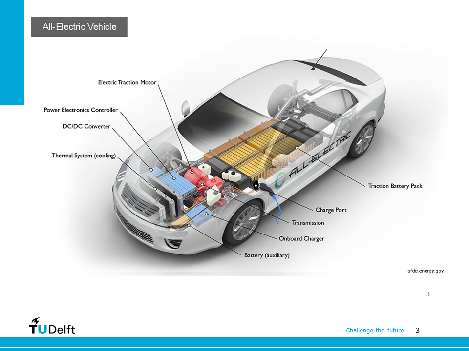
We start this lecture with the EV system again. You may notice that there is a DC/DC converter between the battery and the traction motor drive
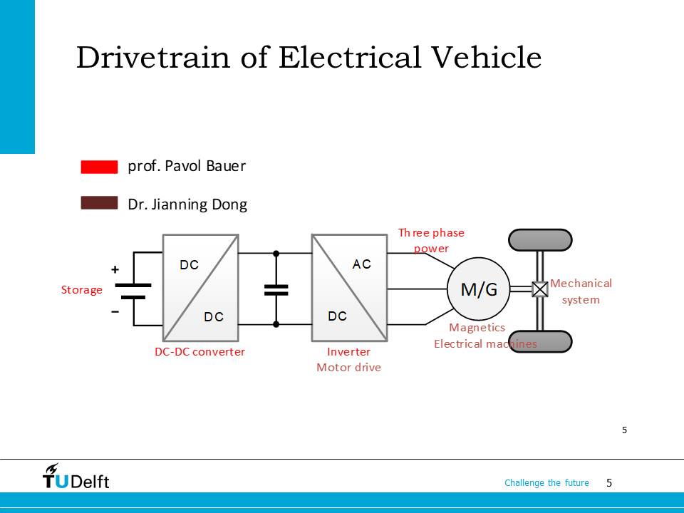
As shown here, the battery voltage is usually equal to or lower than the DC bus voltage of the motor drive (DC/AC converter). Thefore, the DC/DC converter should be able to behave like a boost converter, when the power is flowing from the battery to the motor side. However, when the EV is decelerating, the power flow goes from the motor to the battery since we want to save energy using regenerative braking. Now we need a converter behaves like a buck converter when the power goes from the motor side to the battery side.
In this lecture, we will first study the boost converter, then investigate how to meet the functionalities required above by the EV using a bi-directional DC-DC converter.
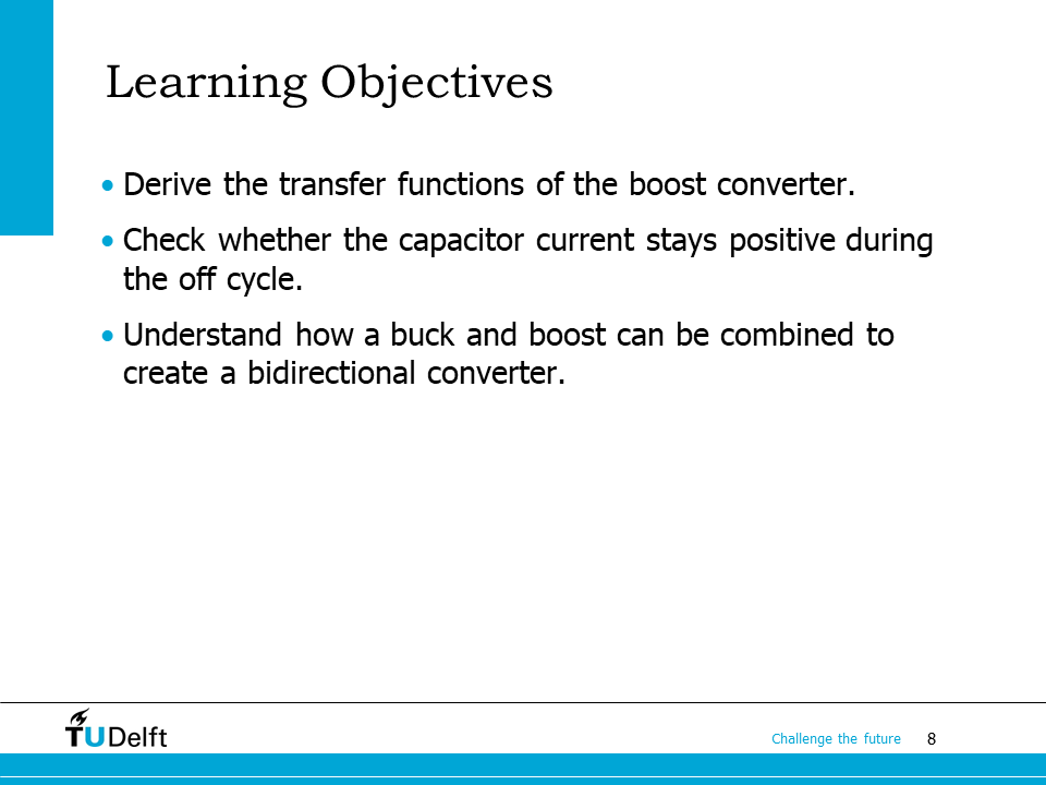
Learning objectives are listed on this slide. After taking the lecture, we will be able to analyze the inductor current, transfer functions and capacitor current of the boost converter, and also understand how a bi-directional DC-DC converter can be realised by combining a buck and a boost converter.
10.1. Boost converter: analysis and waveforms#
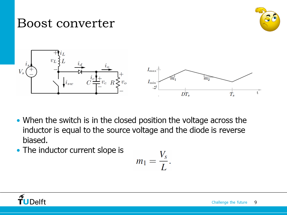
As we briefly discussed in the last lecture. The inductor current in the boost converter still keeps a triangular shape at steady state when CCM assumption is applied. When the switch is closed (on-state), the input voltage is applied across the inductor, so the slope of the inductor current is
Now the diode current is zero since it is reverse-biased by \(v_c\).
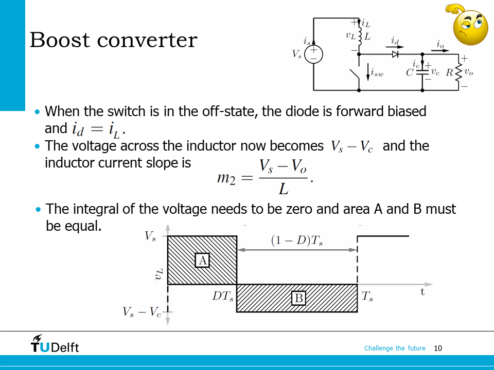
When the switch is open (off-state), the diode is forward biased, and since it is in series with the inductor, \(i_d = i_L\). Now the voltage across the inductor is \(v_L = V_s-V_c\), therefore the inductor current slope is
At steady state, the average voltage across the inductor should be zero, e.g. the shadowed areas A and B should be equal. Based on this we will be able to derive the voltage transfer ratio.
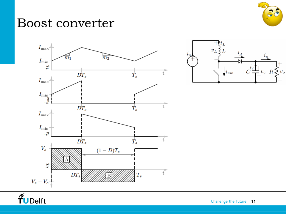
Here it shows the current waveforms of the inductor, switch and diode, and voltage waveform across the inductor in a boost converter respectively.
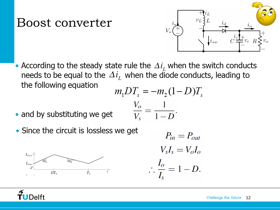
According to the steady state assumption (area of A and B are equal, average inductor voltage is zero, or \(\Delta i_L\) are the same when calculated from two slopes), we have
so the voltage transfer ratio is solved
Since ideal components are used, the circuit is lossless, so we have
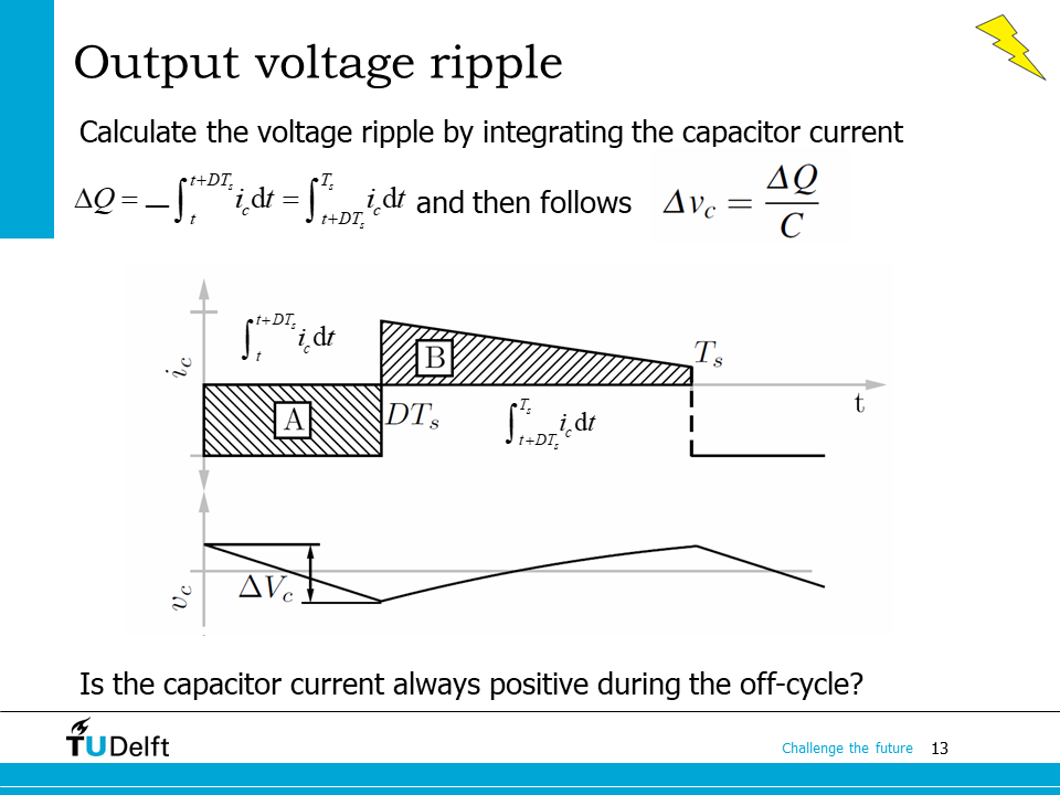
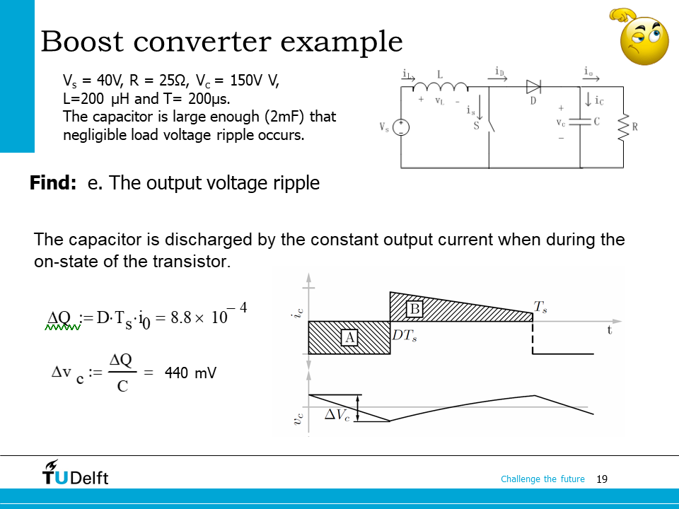
Then let us study the output voltage ripple. Again, we can derive it from the change in charge, the same way as we did for the buck converter.
When the switch is closed, the diode is reverse biased, so only the capacitor supplies the load. The capacitor current is considered to be the same as the output current, but with with opposite polarity. The total charge leaves the capacitor during the on state is
When the switch is open, the diode is forward biased, the current goes into the capacitor is the difference between the inductor current and the output current. The total charge goes into the capacitor during the off state is
The above two equations should be equal, i.e.,
and we know \(I_L = I_{s}\), so \(\frac{I_s}{I_L} = 1-D\), which agrees with the current transfer ratio as we derived from power equivalence on the last slide.
During the off cycle, the minimal current goes into the capacitor is
Apparently, when the input current \(I_s \geq \frac{V_sT_s}{L}\), or output current \(I_o \geq (1-D)\frac{V_sT_s}{L}\), the capacitor current during the off-cycle (area B) does not go negative. As the waveform shown here, the accumulated and released charge in one cycle is
The output voltage ripple is
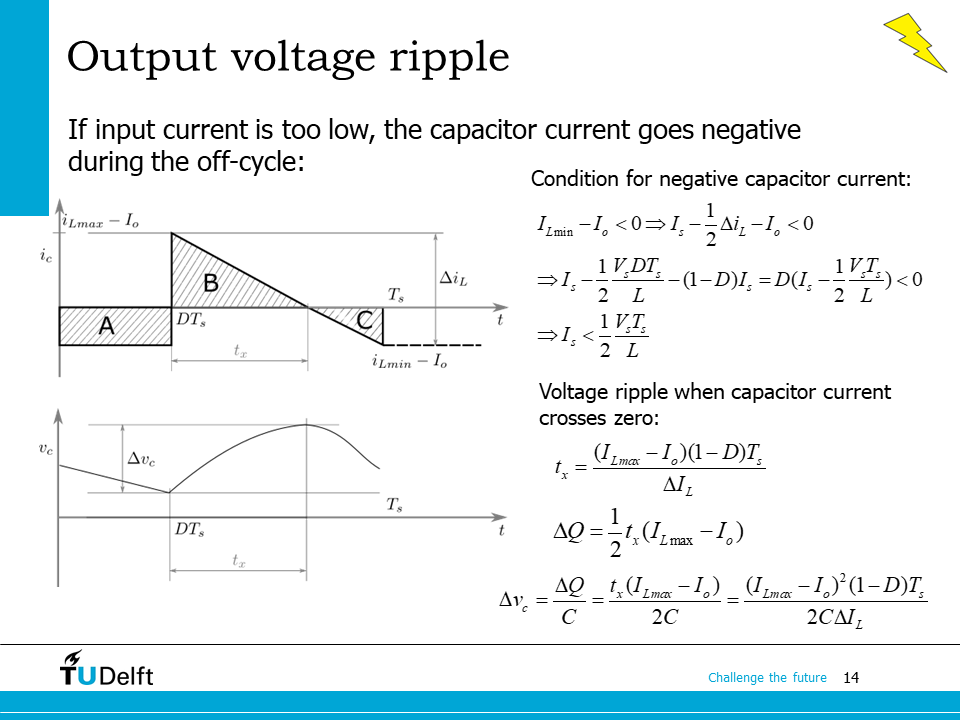
If \(I_s < \frac{V_sT_s}{L}\) or \(I_o < (1-D)\frac{V_sT_s}{L}\), the minimal inductor current will be smaller than the output current, the capacitor current during the off cycle will go negative. To calculate \(\Delta v_c\), the area of the triangle B should be solved to calculate the accumulated charge \(\Delta Q\) during the time interval \(t_x\).
\(t_x\) can be calculated from triangle proportionality:
Then the charge added to the capacitor during \(t_x\) is calculated from the
\(\Delta v_c\) is
Note
Average current through the capacitor in one cyle is zero, i.e., \(Area_{A} + Area_{C} = Area_{B}\) still holds under steady state, even in this situation. You may try to prove it yourself.
10.2. Boost converter example#
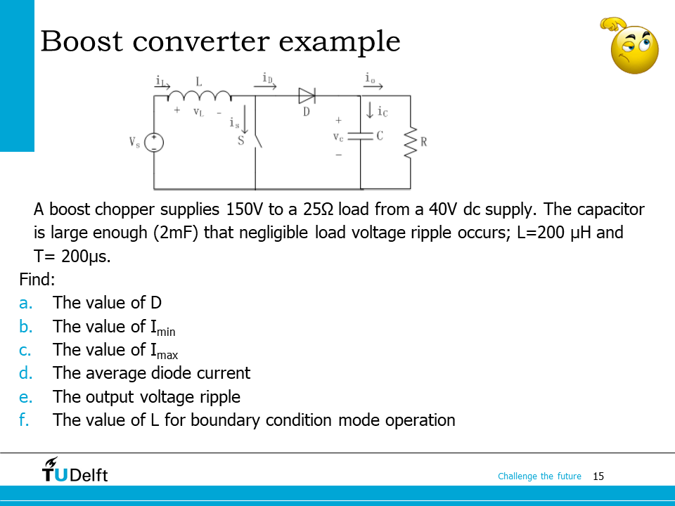
This example help you practice all necessary calculations you are supposed to be able to do after taking the lecture. Please first try to work out yourself and click the block and code below for answers.
Click here for solution
Show code cell source
# boost converter parameters
Vo = 150;
Vin = 40;
R = 25;
C = 2e-3;
L = 200e-6;
Ts = 200e-6;
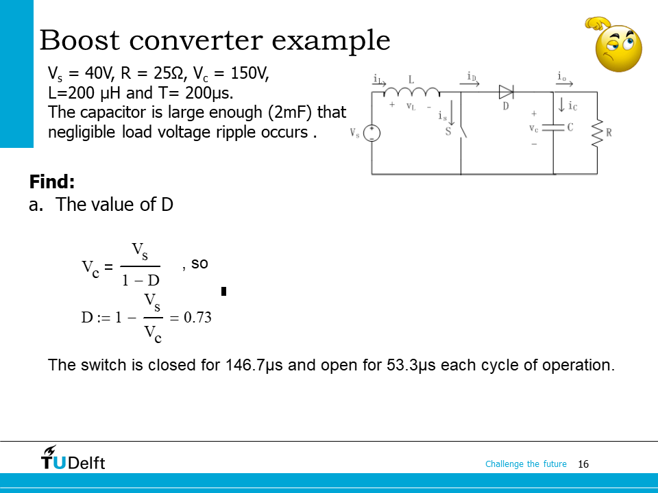
# Vo/Vin = 1/(1-D)
D = 1 - Vin/Vo;
print('a. the duty cycle is {:.3f}.'.format(D))
# average input current, same as average inductor current
Io = Vo/R
ILav = Vo*Io/Vin; # power balance
dIL = D*Ts*Vin/L;
# max current
ILmax = ILav + dIL/2;
# min current
ILmin = ILav - dIL/2;
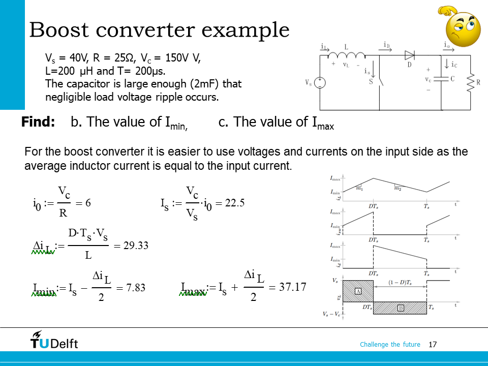
print('b. the max current is {:.3f} A.'.format(ILmax))
print('c. the min current is {:.3f} A.'.format(ILmin))
# diode current: only flows when switch is off for boost
# and when switch is off, current the same as inductor
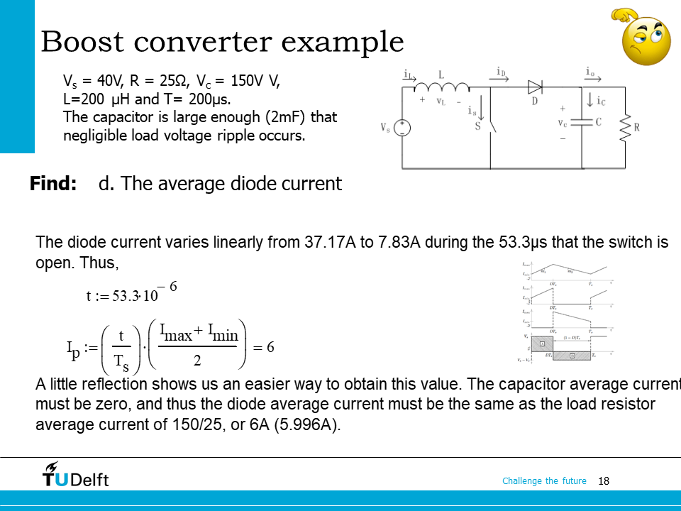
# since the capacitor average current is zero, Idav should also be equal to the output current
Idav = ILav * (1-D)
print('d. the average diode current is {:.3f} A.'.format(Idav))
# since the minimal inductor current is above output current,
# so that capacitor current does not go negative
dV = D*Ts*Io/C
print('e. the voltage ripple is {:.3f} V.'.format(dV))
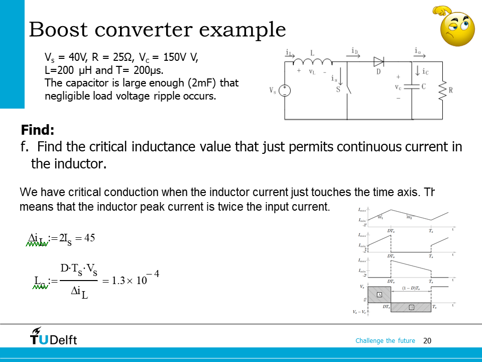
# boundary condition for inductor current happens when the minimal current is zero,
# so average is half of maximum
dIL = 2*ILav
LB = D*Ts*Vin/dIL
print('f. the boundary condition inductance is {:.3f} uH.'.format(LB*1e6))
a. the duty cycle is 0.733.
b. the max current is 37.167 A.
c. the min current is 7.833 A.
d. the average diode current is 6.000 A.
e. the voltage ripple is 0.440 V.
f. the boundary condition inductance is 130.370 uH.
10.3. Bidirectional converter#
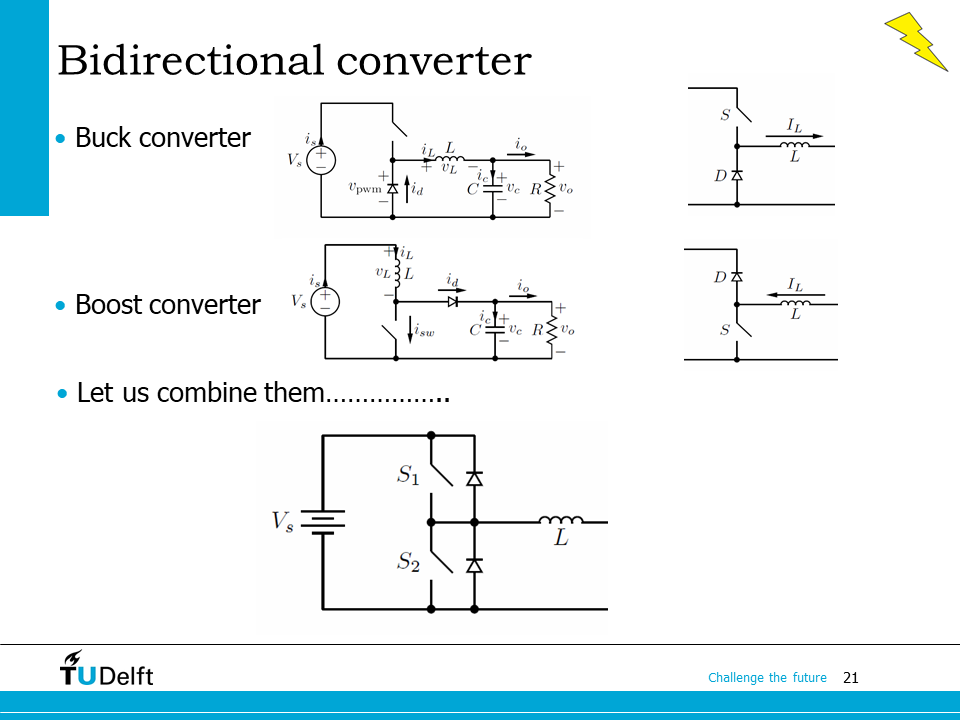
The last topic for this lecture is the bidirectional converter. As we mentioned in the beginning of the lecture, there are applications require a bidirectional power flow. For example, the battery should be able charged and discharged during the regenerative braking and acceleration.
By observing the the buck converter and the boost converter, it can be observed that in both of them, the inductor is connected to the node between the diode and the swtich. If we connect the two converters in parallel and combine the inductors into one, we will be able to obtain a converter on the bottom side of the slide, where the two switches are connected in series, and two anti-paralleled diodes are connected to them respective. The inductor is connected to the node between the two switches. This topology forms a bidirectional converter, and is also called a half bridge.
If current flows from left to right, the converter works as a buck converter, otherwise it works as a boost converter if current flows from right to left.
We will study the topology in detail in the next lecture.