24. Synchronous Machine Performance#
After understanding the structure and operation principle of the synchronous machine, we will study the performance calculation of the synchronous machine further. We will start with equivalent circuit and phasor analysis base don it. In the end we will introduce the definition of power angle and study how the performance of the synchronous machine changes with power angle.
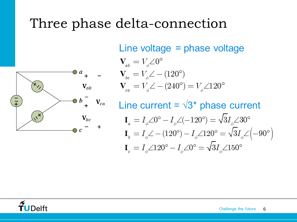
24.1. Three phase recap#
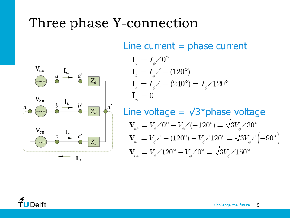
It is essential to know the three phase related calculation by heart when analysing three phase AC machines.
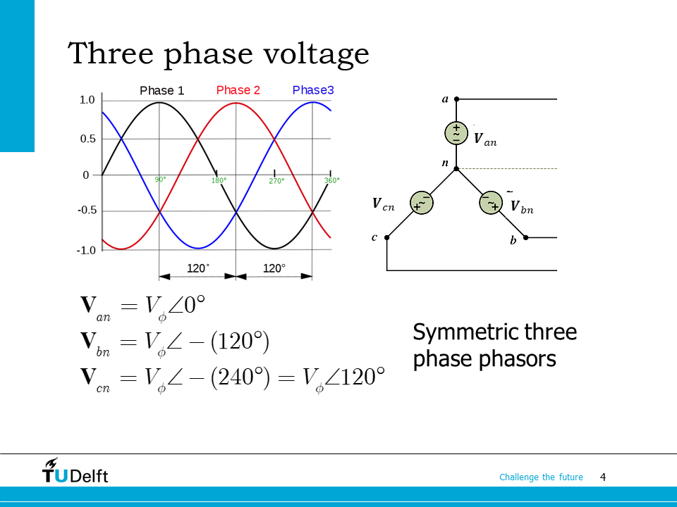
You may use the following three slides to review the relationship between the line to line quantities and phase quantities, for both \(Y\) connected and \(\Delta\) connected three phase systems.
24.2. Synchronous machine phasor diagram#
Now let us go one step further based on the equivalent circuit by analysing its phasor diagram.
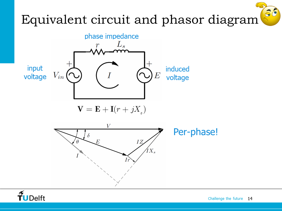
On this slide, the input voltage phasor is \(\mathbf{V}\), the induced voltage phasor is \(\mathbf{E}\). \(r\) and \(j X_s = j\omega L_s\) are the phase resistance and the synchronous reactance respectively. Phase complex impedance is \(\mathbf{Z}= r+jX_s\). \(\mathbf{E}\) is the induced voltage phasor. Following the motor notation, we can derive the phasor diagram on the bottom.
In the phasor diagram, the angle phase current phasor leading the phase voltage phasor \(\theta\) is the power factor angle. The angle the phase induced voltage phasor leading the phase input voltage phasor \(\delta\) is defined as the power angle.
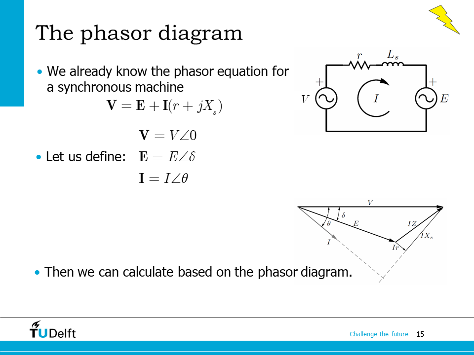
From the equivalent circuit, following the motor notation, we know
\(\mathbf{V} = \mathbf{E} + \mathbf{I}(r+jX_s).\)
Assuming the phase angle of the input voltage phasor is 0, so \(\mathbf{V} = V\angle 0\), then the other two phasors are
24.3. Power angle#
Based on the defined power angle \(\delta\), we are able to study the power flow of the synchronous machine.
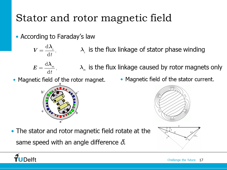
From Faraday’s law, we know the phase voltage is the time differential of the stator phase flux linkage \(\mathbf{\lambda}_s\), which includes the contributions from both the rotor magnetic field, and that generated from stator three phase currents.
The induced voltage, however, is the time differential of the flux linkage contributed from the rotor magnetic field only \(\mathbf{\lambda}_m\).
Since the phase \(\mathbf{E}\) leading \(\mathbf{V}\) is the power angle \(\delta\), we can see that the electrical angle the rotor flux leading the stator flux is also \(\delta\). Therefore, the power angle \(\delta\) is in essence the electrical angle the rotor flux leading the stator flux.
Furthermore, we can conclude that if \(\mathbf{V}\) leads \(\mathbf{E}\), i.e., the stator flux leads the rotor flux (\(\delta < 0\)), the synchronous machine operates as a motor, otherwise if the stator flux lags the rotor flux (\(\delta > 0\)), the synchronous machine operates as a generator.
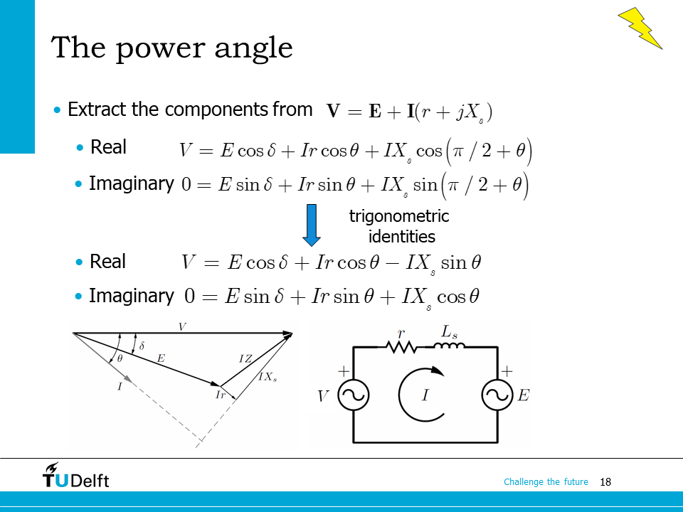
Let us validate the above conclusions using mathematical derivation. We rewrite the phasor equation \(\mathbf{V} = \mathbf{E} + \mathbf{I}(r+jX_s)\) in its real part and imaginary part, we have.
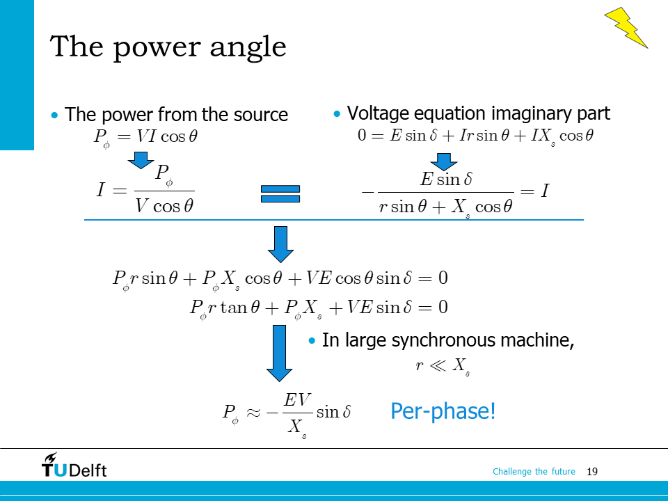
We know the per-phase power from the source is
which leads to \(I = \frac{P_\phi}{V\cos\theta}\).
From the imaginary part of the voltage equation we derived on the last slide, we have
The two currents should match each other, so we have
which gives rise to
Dividing the equation above by \(\cos\theta\), we have
In large synchronous machines, usually the phase resistance is far less than the synchronous reactance, \(r \ll X_s\), thus negligible, the equation above can be simplified as
or
Note
The power here is the input power per phase neglecting the phase resistance. In order to obtain the total power, it has to be multiplied by number of phases.
In some textbook, the power angle \(\delta\) is defined as the angle \(\mathbf{V}\) leading \(\mathbf{E}\), instead of \(\mathbf{E}\) leading \(\mathbf{V}\), or the generator notation is followed instead of the motor notation. In such case, the minus sign has to be removed, i.e., \(P_\phi \approx \frac{EV}{X_s}\sin\delta. \).
24.4. Power transferred by a synchronous machine#
Based on the defined power angle, we can analyse how the power flow inside the synchronous machine changes as a function of the power angle.
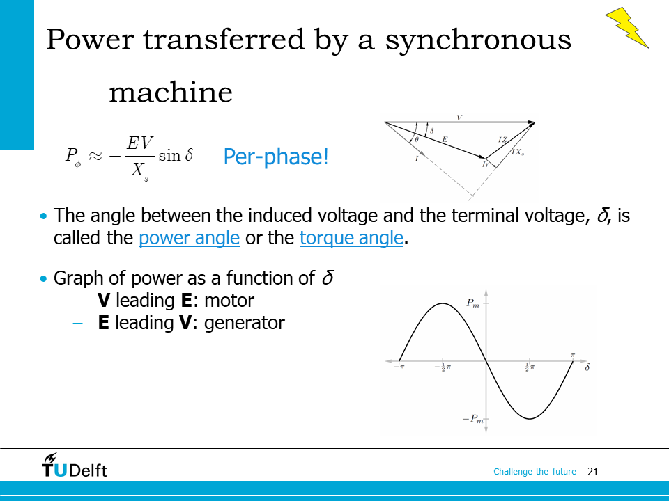
The power angle \(\delta\) is also called the torque angle, since the electromagnetic torque \(T_{em}\) is also a function of \(\delta\):
where \(\omega_m\) is the rotor mechanical angular speed of the synchronous machine. Here a factor of 3 is included since \(P_\phi\) is only the power of one phase.
The figure on the bottom shows the power angle curve of a synchronous machine, which shows how the input power changes as a function of the power angle. As we can see, if \(\delta <0\), the machine operates as a motor, otherwise as a generator.
The maximum generating or motoring power can be achieved at \(\delta = \frac{\pi}{2}\) and \(\delta = -\frac{\pi}{2}\) respectively, which is corresponding to the condition when the stator and rotor magnetic flux form an angle of \(\frac{\pi}{2}\).
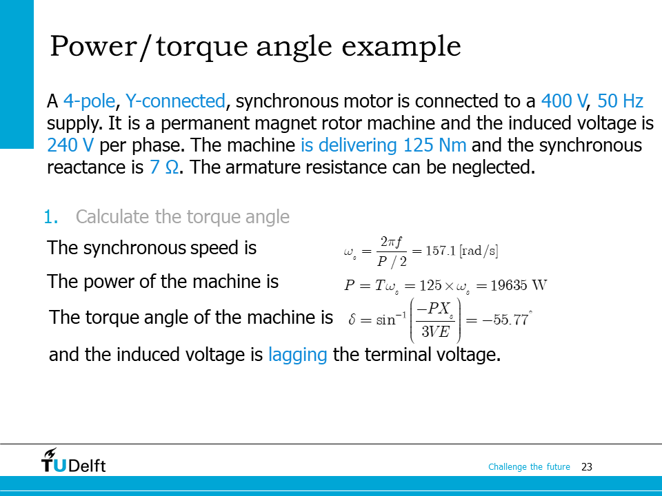
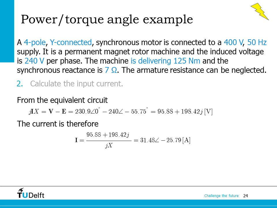
The example here shows how the power angle is used in synchronous machine performance calculation. Please try to solve it yourself and click to show the script below for the right answer.
Click to show the answer.
Show code cell source
import numpy as np
from IPython.display import display, Markdown, Math, Latex

P = 4 # number of poles
p = P/2 # number of pole pairs

V_ll = 400.0  # line-line voltage
f   = 50.0 # frequency
E_phi = 240.0 # induced voltage
Tem = 125.0 # torque
Xs  = 7.0   # synchronous reactance

# 1. torque angle
omega_m = 2*np.pi*f/p # synchronous angular speed
P_phi   = Tem*omega_m/3 # power per phase
V_phi   = V_ll/np.sqrt(3)

delta   = np.arcsin(-P_phi*Xs/(V_phi*E_phi))
print(f'1. The torque angle is {delta/np.pi*180:.2f} degree.')

# 2. input current
# phasors
V_phi_phs = V_phi
E_phi_phs = E_phi*np.exp(1j*delta)
I_phi_phs = (V_phi_phs - E_phi_phs)/(1j*Xs)
print(f'2. The input current phasor is {I_phi_phs:.2f} A, or')
display(Math('$\mathbf{{I}}_\phi={:.2f}\\angle{:.2f}^\circ \mathrm{{A}}$'.format(abs(I_phi_phs), np.angle(I_phi_phs)/np.pi*180)))
1. The torque angle is -55.75 degree.
2. The input current phasor is 28.34-13.70j A, or