1. Introduction to Electrical Energy Conversion#
1.1. History and energy conversion types#
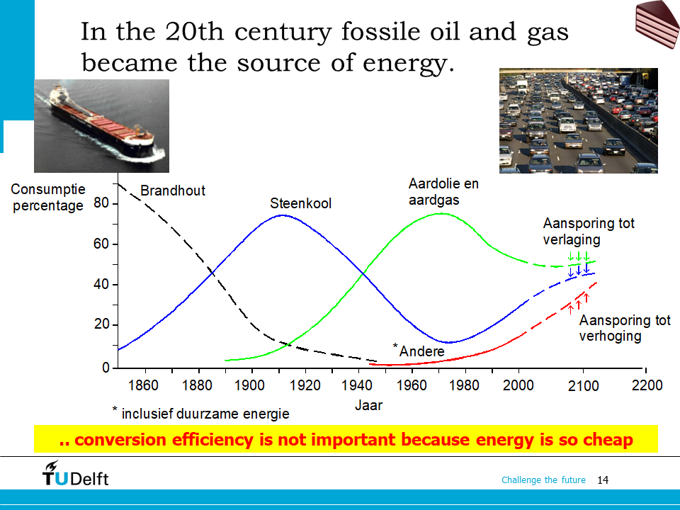
Dear students, let’s start the lecture by studying a bit into the history of energy conversion. In the 20th century, fossil fuels (oil and gas) are extensively exploited and used, as can be seen in the slide below. By then people did not care much about the energy conversion efficiency: internal combustion engines (ICE), the efficiency of which is rarely above 40%, are widely used for various applications.
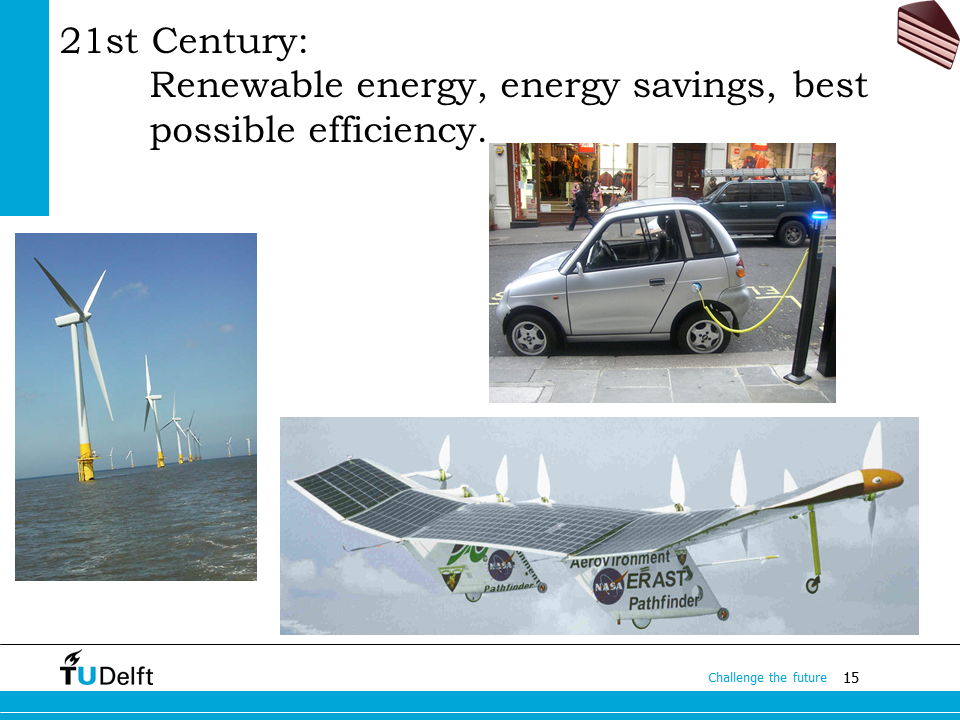
In the last 40 years, especially since the beginning of the 21st century, renewable energy sources have drawn more and more attention, mainly because of environmental concerns. Energy conversion efficiency is also boosted by applying more and more electrical energy conversions. The motivation behind it is the pressure from climate change, pollution, and higher energy cost. Today we will give a introduction to the electrical energy conversion system.
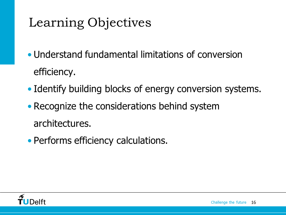
The learning objectives of our first lecture are listed above. We will start with fundamental limitations of energy conversion, basic building blocks of electrical energy conversion systems, then move on to see how to use these blocks to form the system architecture, and the considerations behind various architectures. At the end of the lecture, we will also show how to do efficiency calculation for electrical systems using examples.
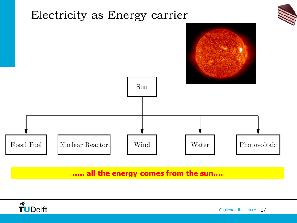
All the energy comes from nuclear reactions, taking place either in the sun or on the earth. Fossil fuel is the stored energy from the sun millions of years ago in the form of fossils. Water energy (hydro-energy) comes from stored sun energy as a consequence of vaporisation. Wind energy is brought by the evenly heating of the air by the sun.
The energy coming from water, wind and solar radiation are called renewable because it cannot be depleted. Fossil fuels, on the other hand, while a cheap (in price, but not in environmental and climate impact) and easily available source of energy, can only be consumed once and are being depleted.
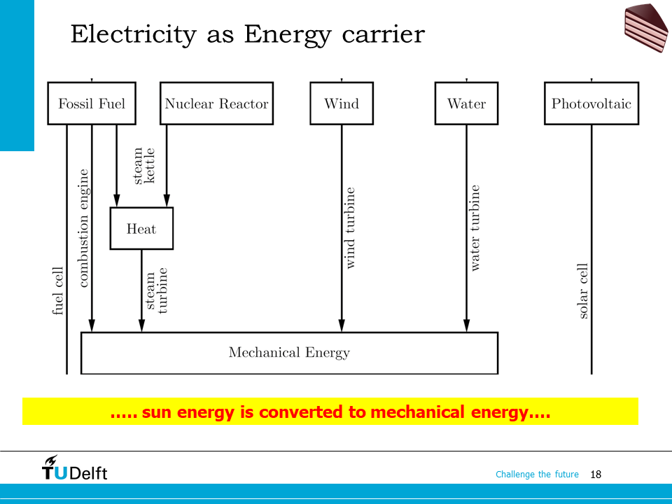
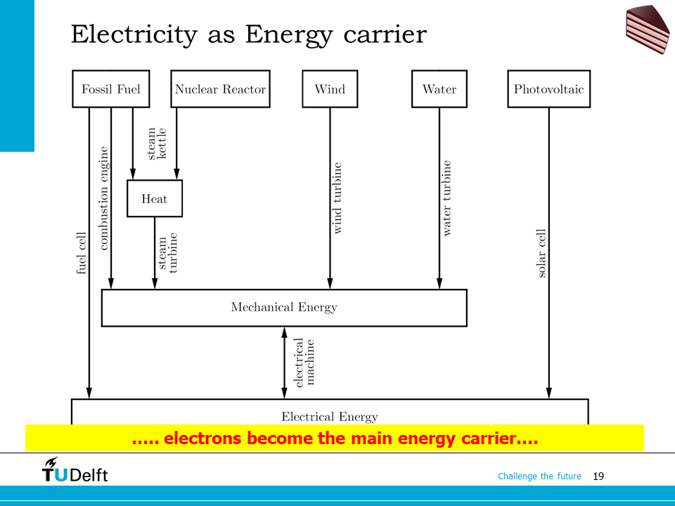
Let’s take a look at how the energy is normally used nowadays. Most of the energy is first converted into mechanical energy as an intermediate step before it is converted into electrical energy. Then electrical machines are involved to convert the energy further to electricity, which will be studied in this course later. Fossil fuels like natural gas can also be converted directly to electricity via the electrochemical process in fuel cells. Solar energy can do the same by the photovoltaic process in solar cells.
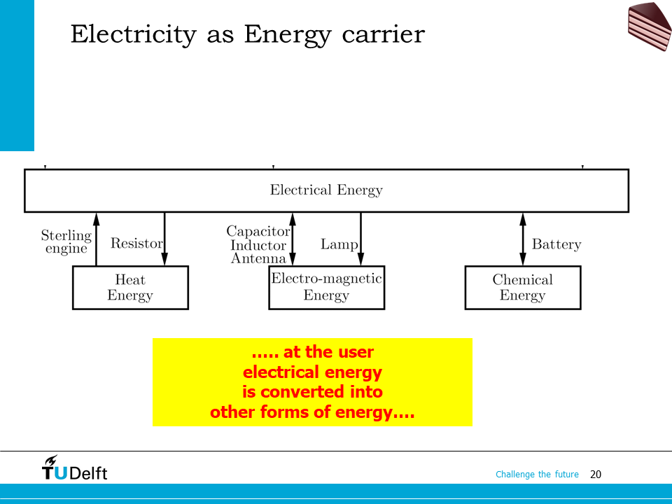
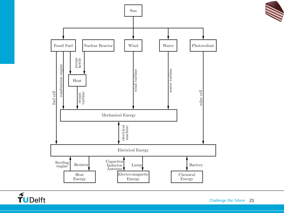
Once we have the energy converted to electricity, it becomes very flexible. We are able to convert electrical energy to various types of energy by applying different electrical components. That’s one of the advantages electrical energy conversion has compared to other forms of energy conversion. Do note that the energy conversion flow can be bi-directional for most of the conversion processes.
1.2. Thermodynamic and energy conversion efficiency#
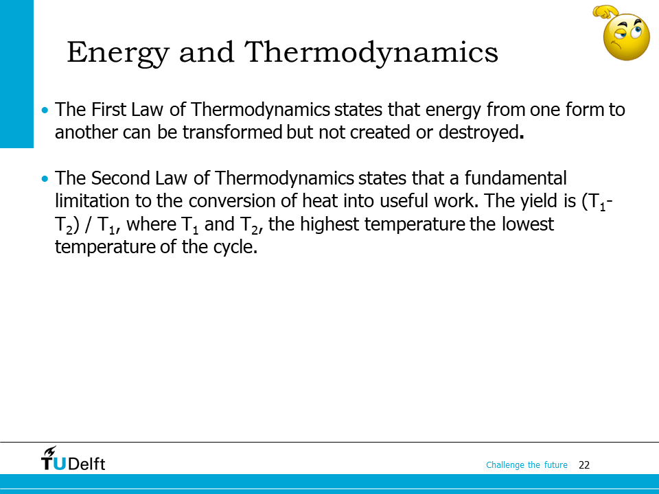
All the energy conversion processes have certain efficiency. As the first Law of Thermodynamics states, the energy cannot be created or destroyed, i.e., the efficiency can not be above 100%, or a perpetual motion machine of the first kind does not exist.
The second Law of Thermodynamics says the yielded energy is limited to the ratio between temperature difference in this cycle to the highest temperature, which indicates the efficiency of converting heat to work is always below 100%, or a perpetual motion machine of the second kind does not exist.
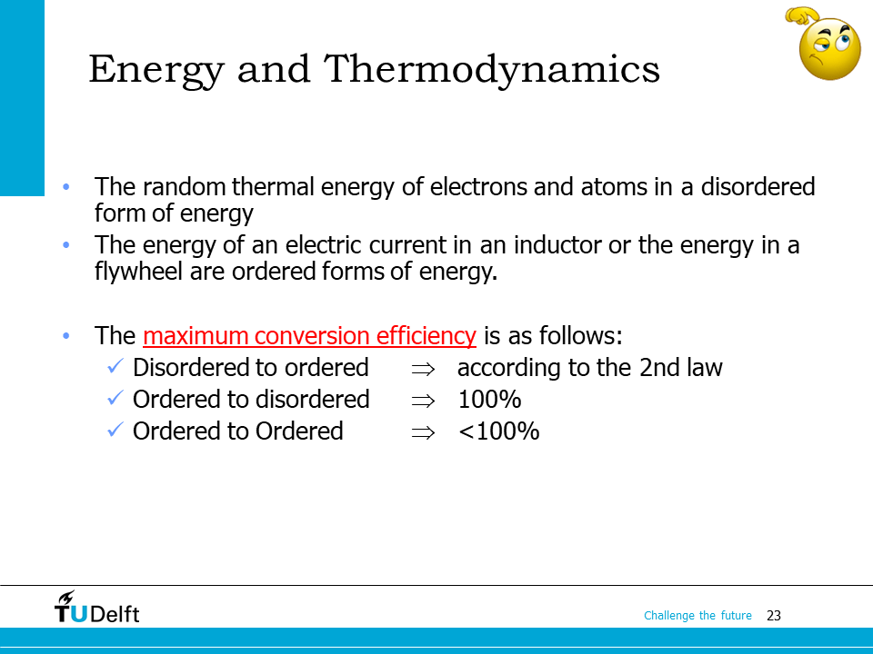
We can categorize the energy into the disordered and ordered depending on whether the electrons and atoms involved are ordered or in a disordered form. For example, the thermal energy, i.e., the energy stored in the heat, is disordered since it is reflected by the random movement of the electrons and atoms. The electrical energy stored in an inductor is ordered, since all the electrons are flowing in an ordered form governed by the current. The mechanical energy stored in a flywheel is also ordered, since or atoms are rotating in the same pattern.
Depending on the categories of the energy forms, we have different theoretical efficiency limits of energy conversion. From disordered to the ordered form, the efficiency is bonded by \((T_1-T_2)/T_1\), the 2nd Law of Thermodynamics. From ordered to disordered (e.g., electrical energy stored in an inductor to heat), the upper boundary is 100%. From ordered to ordered, the efficiency limit is below 100%, since the non-ideal and parasitic phenomena, e.g., heat is also generated when we are transforming electrical energy from one voltage to another.
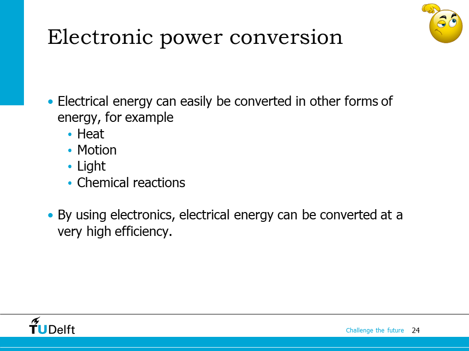
In summary, electrical energy can be converted easily to other forms of energy, at a cost of loss. However, compared to other forms of energy conversion, the efficiency is very high, especially when electronics are involved in the conversion, which is going to be covered in our course.
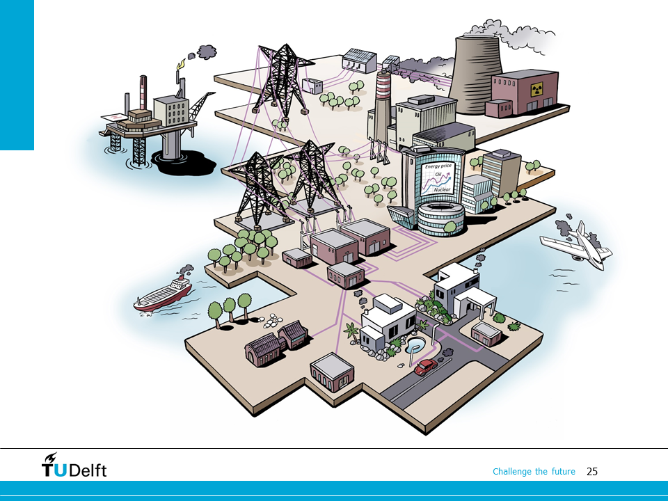
This drawing shows the enregy conversion scenario as of today. As we can see, thermal energy conversion is used for electricity, aviation, shipping and households, which has its limit in efficiency by nature, and brings CO2 and pollutions.
Here it shows the future scenario we are working towards. Actually, part of the scenario is already happening. We will use more and more high efficient electrical energy conversion for various sectors and more renewable sources will be used for electricity.
1.3. Electrical energy conversion systems#
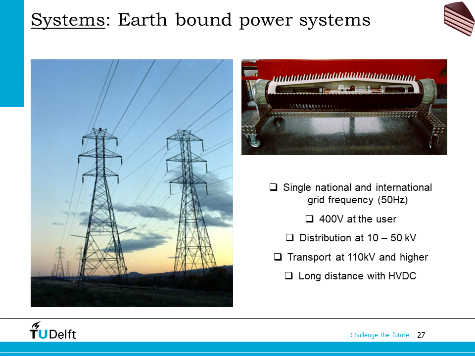
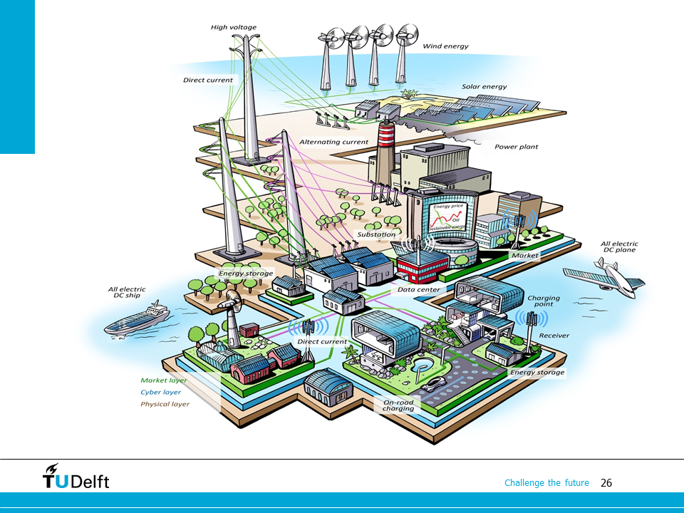
Now let’s see different types of electrical energy conversion systems used in our daily life. The electric power grid is probably the largest man-made system we have on this planet.
The power grids are usually managed per nation, with international inter-connections in between. The currents flowing in the power grids are usually alternating current (AC). The alternating frequency is 50 Hz in Europe, but can be different in other parts of the planet, e.g., it’s 60 Hz in United States. At the user side, the voltage level is 400 V for line-to-line voltage of the three-phase system, which we will study in the next module of the course. For single phase, the voltage becomes \(400/\sqrt{3} = 230~\mathrm{V}\).
To save energy, higher voltage is needed to transfer the electricity from one place to another. In the distribution scale, e.g., from substations to users, it’s usually 10-50 kV. For longer distances, the transport voltage level is 100 kV or higher. If a very long distance of transport is needed, e.g., from some offshore wind farms to the shore, high voltage DC (HVDC) is used to replace AC because of lower cost of transmission (2 conductors vs. 3 conductors), no reactive power and lower losses (no radiation and induction losses).
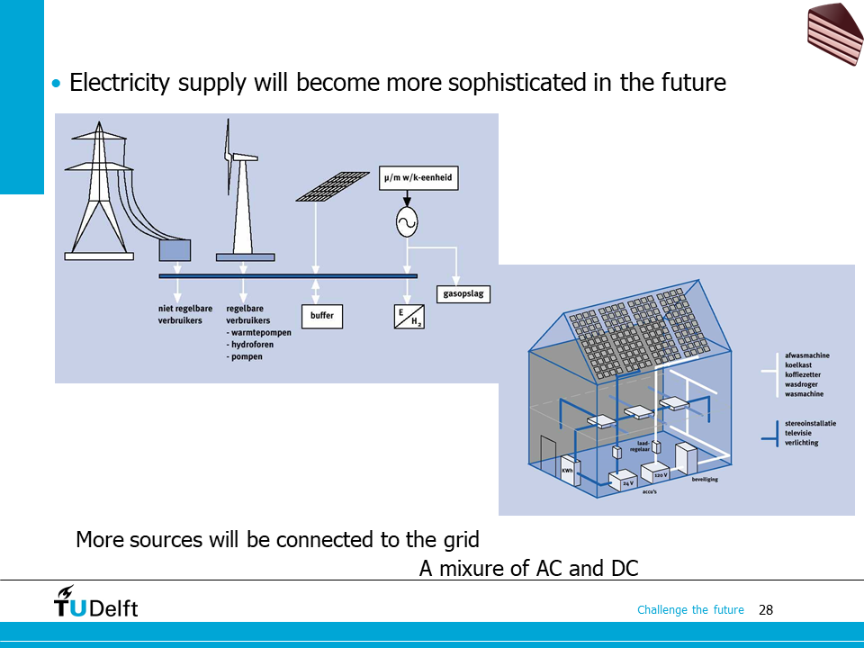
The electric power grid is also evolving. It’s getting more and more sophisticated. More renewable sources will be connected to the grid, and there will be a mixture of AC and DC connections both in our households and electricity transmission.
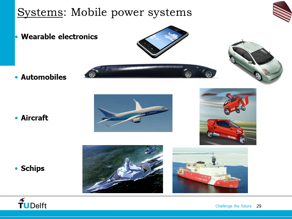
There are also mobile electrical energy conversion systems. In our cell phones, cars, aircraft and ships, we can find electrical energy conversion systems everywhere.
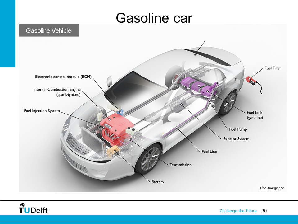
Even in a gasoline powered car, we still have electrical systems for the radios, doors, ventilation etc.
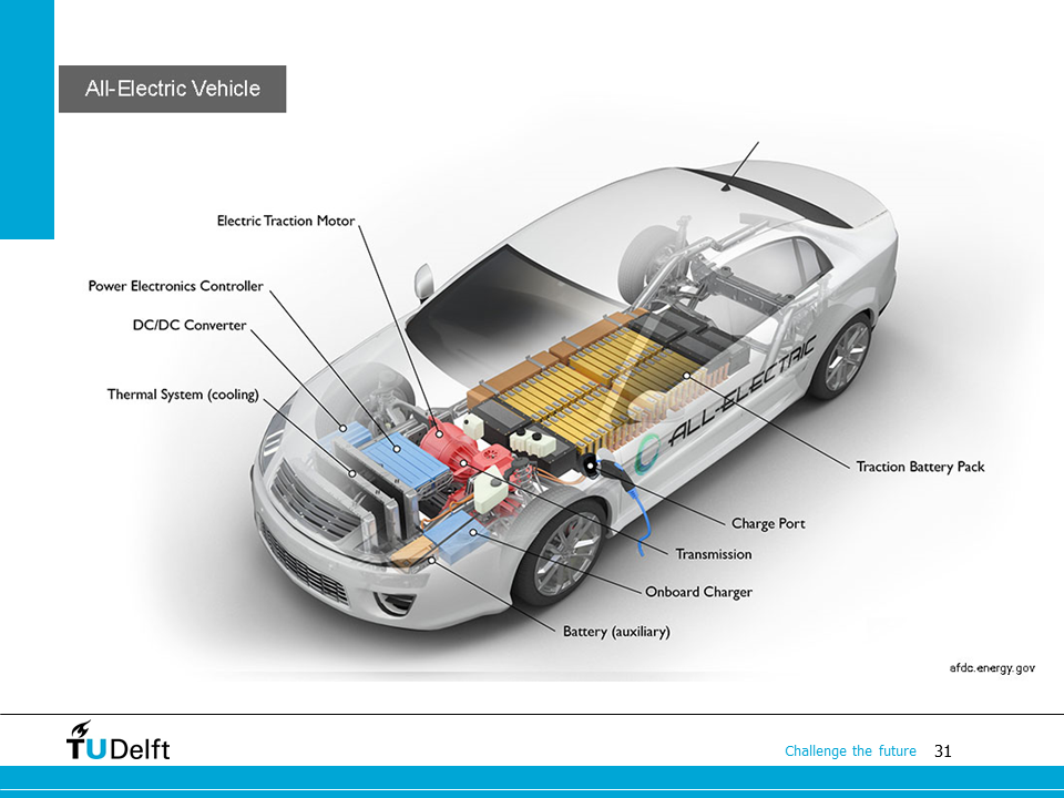
The electric car becomes a trend now. As you can see here. The electrical system is more complicated compared to a gasoline car. The propulsion is also provided by electricity, so a large amount of batteries is needed to replace the gasoline tank to store energy.
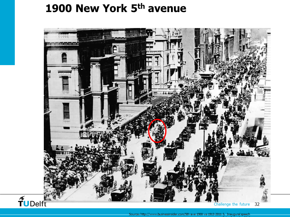
Well, the electric car is not a new concept. Here it shows the street view of New York in 1900, as you can see the only non-horse powered car in the middle is an electric one.
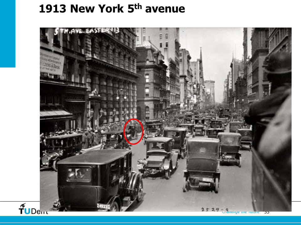
However, 13 years later, on the same street, the horse powered car becomes the only one. But sooner after that, because of the advances in internal combustion engine (ICE), and the introduction of starter motor (an electric motor to start the ICE replacing hand-cranking), ICE cars become dominant.
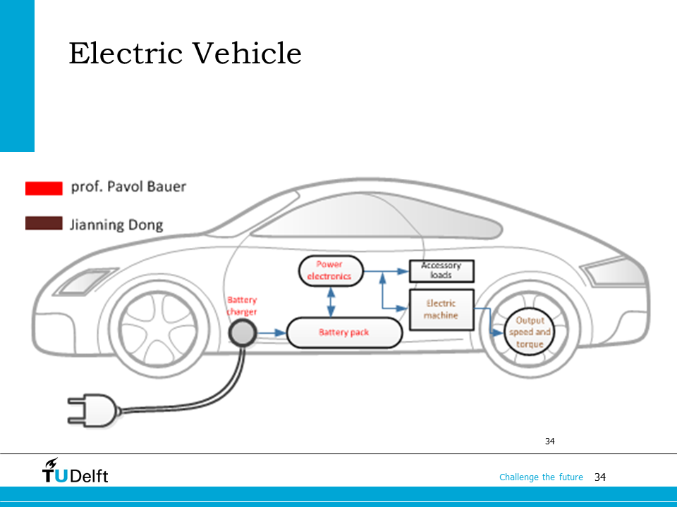
Starting from 2008, a renaissance in electric vehicle manufacturing occurred due to advances in battery technologies, and the pressure to reduce greenhouse gas emissions and improve air quality. In this course, we will constantly use the figure of an electric car here to show the relevance of different modules of the course.
In the coming weeks, Prof. Pavol Bauer will give you lectures on electrical energy storage and power electronics, while Dr. Jianning Dong will give you the lectures related to magnetics, mechanical systems, and electrical machines.
1.4. Energy conversion building blocks#
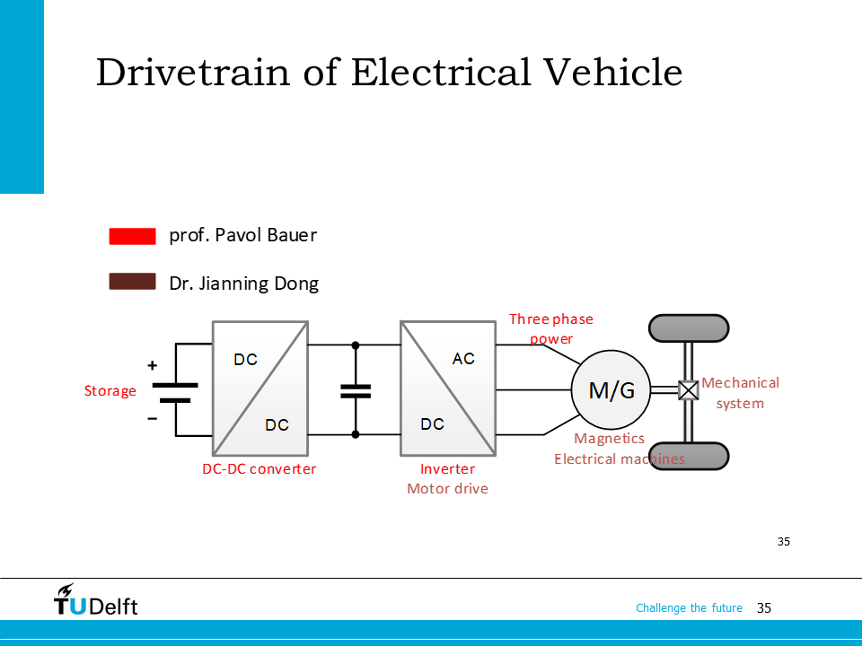
This figure shows the drivetrain of the electric car and the corresponding content that is going to be learnts in this course.
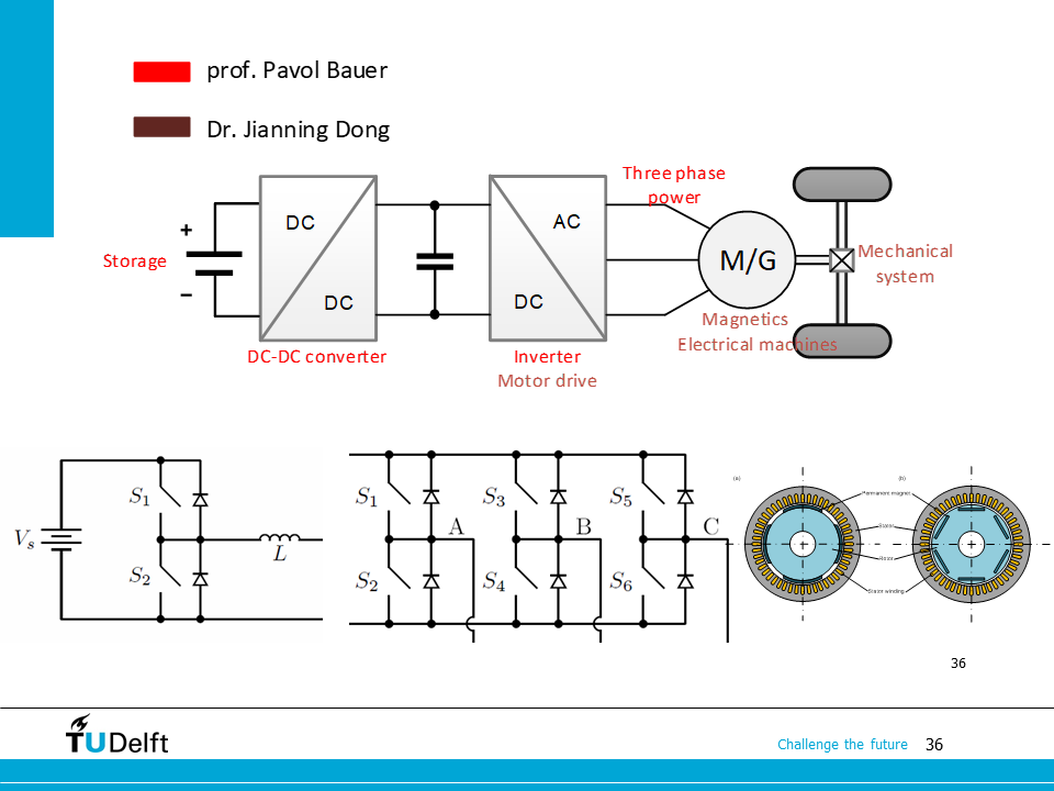
More specifically, we will study the electrical energy storage, which is corresponding to the battery. The DC-DC converter between the battery and the DC bus which changes the voltage level, the inverter which is converting DC to AC to power the motor, the electrical machines and the mechanical transmission system one by one.
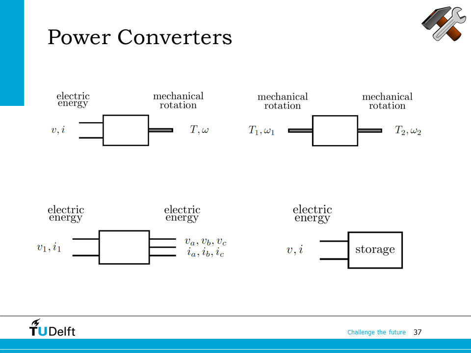
We could also use blocks to represent the involved energy conversion processes in the electric car, as shown in this slide.
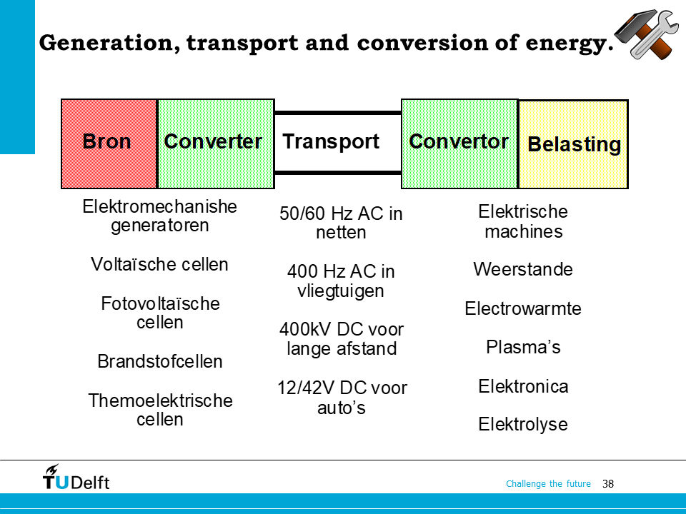
This slide gives an overview of the electrical energy conversion process with annotations in Dutch. We start from various types of energy sources (bron), and convert them to electrical energy, then transport the electricity via the power grid (netten) to the end-users. Then the users apply converters to utilize electrical energy in various applications.
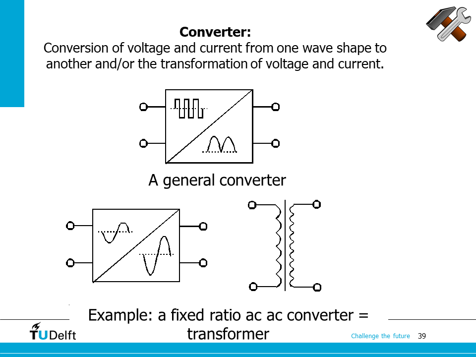
The electric power converters shown in the previous slides are important building blocks in modern energy conversion. The functionality of it is to convert voltage/current from one wave shape to another. For example, from DC to AC, or vice versa. A transformer transforms the amplitudes of the voltage/current at a fixed turns ratio without altering the waveforms, so we can call it a fixed ratio AC-AC converter.
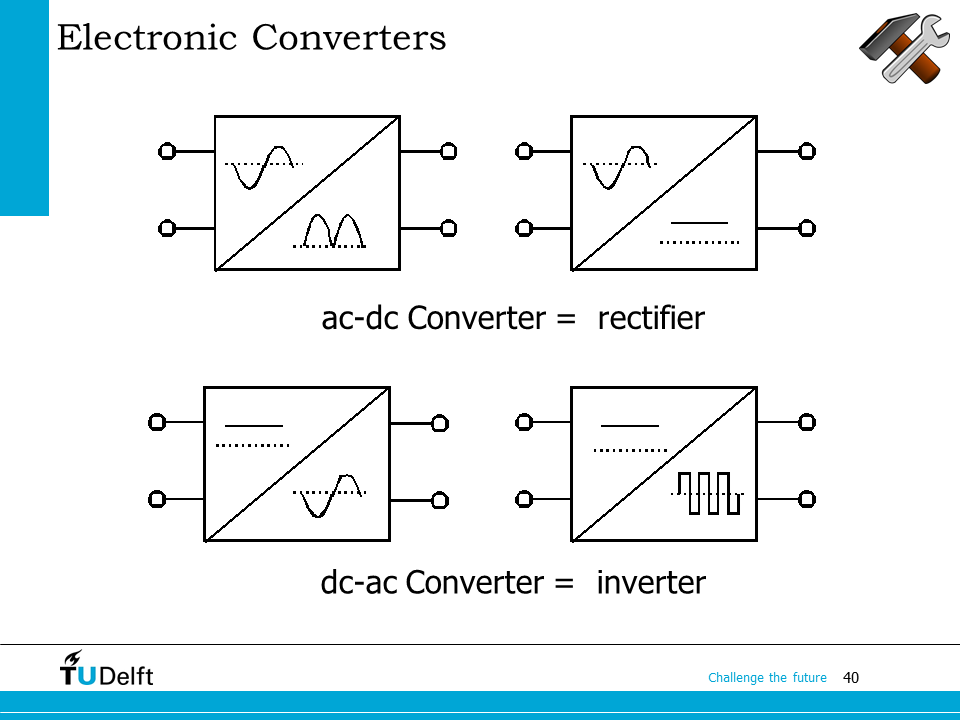
For the converter converting AC to DC, we call it a rectifier. The inverted device, which is converting DC to AC, is called an inverter.
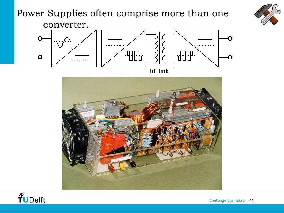
Modern power supplies often has multiple converters in one device. For example, here it shows an isolated DC-DC converter, where the DC power is first converted to high-frequency AC using an inverter, as indicated by the square waveforms in the schematic, then is transformed to another voltage level using a transformer, in the end, the high frequency AC voltage is converted to DC again using a rectifier. People do the DC-DC conversion in this way to provide galvanic isolation in between and the high-frequency link helps reduce the size of the device. We will explore this later in the magnetics part of the course.
1.5. Energy conversion architecture and efficiency#
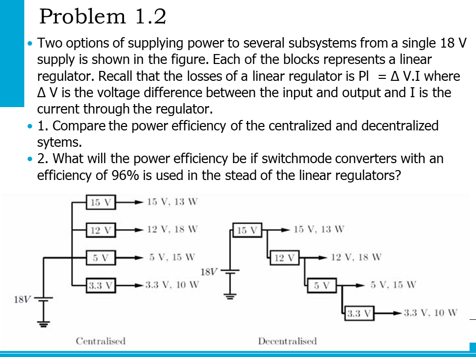
There are different architectures for electrical energy conversion systems and the efficiency may vary depending on different choices on system architecture. Let’s explore it using the problem in the slide.
The problem compares a centralised power supply and a decentralised supply. The key difference is the centralised architecture converts all outputs from one single input directly, while in the decentralised one, the voltage is converted in a levelized manner.
There are also two options for the voltage conversion, one is to use a linear regulator, where the conversion is done by a resistance voltage divider, which is very lossy. The loss is \(\Delta V I\) . The second option is to use a switched-mode power supply, which has a constant efficiency of 96%.
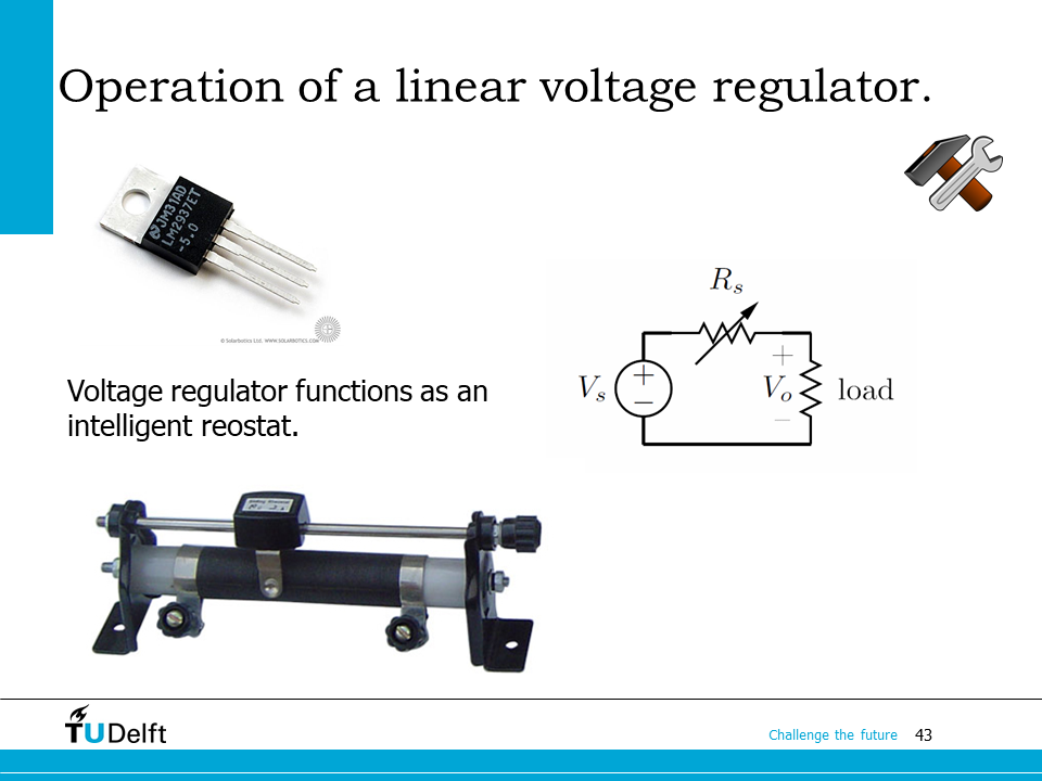
If you do not know what a linear voltage regulator is, please check this slide. The top left corner shows a linear regulator IC, on the right-hand side, the schematic shows the working principle, which is actually the same as the sliding rheostat as you can see on the bottom.
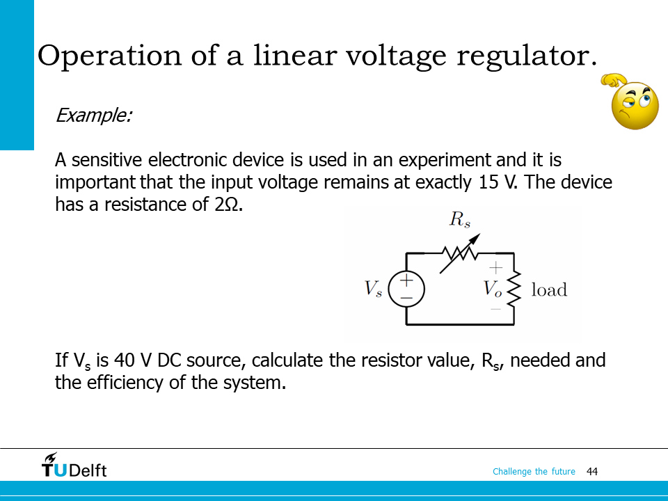
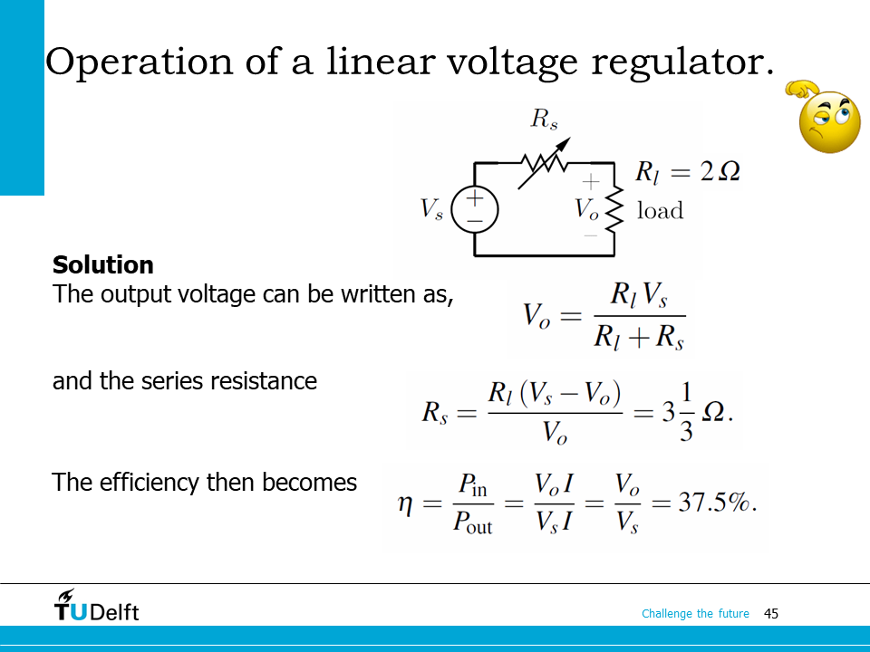
This is a simple example of the efficiency calculation of a linear regulator.
You may first do the calculation yourself and click the block below to check the answer.
Check for solution
Now let’s come back to the more complicated system. How to solve it? Please first try yourself.
Click below for codes and results to solve the problem.
Show code cell source
# Power of different voltage level: p15, p12, p5, p33
# Current of different voltage level: i15, i12, i5, i33
p15, p12, p5, p33 = 13.0, 18.0, 15.0, 10.0
vin, v15, v12, v5, v33 = 18.0, 15.0, 12.0, 5.0, 3.3


i15 = p15/v15
i12 = p12/v12
i5  = p5/v5
i33 = p33/v33

# Total power from input
p_in = vin*(i15+i12+i5+i33)

# Centralized power efficiency with linear regulator
eff1 = (p15+p12+p5+p33)/p_in

print('The efficiency of the centralized system with linear regulator is: {:.2%}'.format(eff1))

# Decentralized, linear regulator
## First calculate the deltaV to get the loss
dvin_to_15, dv15_to_12, dv12_to_5, dv5_to_33 = vin-15, v15-v12, v12-v5, v5-v33
## Total loss should be calculated by summing up all losses on each voltage drop
p_loss = dvin_to_15*(i33+i5+i12+i15)+dv15_to_12*(i33+i5+i12)+dv12_to_5*(i33+i5)+dv5_to_33*(i33)
## efficiency is calculated based on output and the loss
eff2   = (p15+p12+p5+p33)/(p15+p12+p5+p33+p_loss)
print('The efficiency of the decentralized system with linear regulator is: {:.2%}'.format(eff2))
The efficiency of the centralized system with linear regulator is: 37.05%
The efficiency of the decentralized system with linear regulator is: 37.05%
What we learn from it?
The efficiencies for the two architectures are the same. Now let’s look at the case of switched mode power supply with constant efficiency.
Show code cell source
eff_supply = 0.96 # efficiency of the switched mode power supply

# Centralised case,the efficiency for each outpus is the same
pin  = p15/eff_supply+p12/eff_supply+p5/eff_supply+p33/eff_supply
eff1 = (p15+p12+p5+p33)/pin
print('The efficiency of the centralized system with switched mode power supplies is: {:.2%}'.format(eff1))

# Decentralised case,the efficiency of each stage should be considered
pin2 = p15/eff_supply + p12/eff_supply**2 + p5/eff_supply**3 + p33/eff_supply**4
eff2 = (p15+p12+p5+p33)/pin2
print('The efficiency of the decentralized system with switched mode power supplies is: {:.2%}'.format(eff2))
The efficiency of the centralized system with switched mode power supplies is: 96.00%
The efficiency of the decentralized system with switched mode power supplies is: 90.61%
What we learn from it?
As we can see, when switched mode power supply is used, number of conversion stages is critical for high efficient conversion.