23. Synchronous Machine#
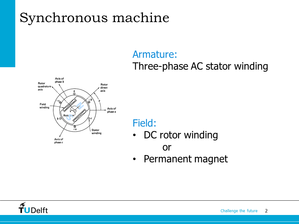
In this lecture, we will study the structure and working principle of the synchronous machine. The stator of the synchronous machine has three phase AC winding, which is also called armature winding. The rotor has either field winding fed with DC current, or permanent magnets to generate magnetic field.
After taking the lecture, we should be able to tell the construction and operation principles of the synchronous machine. We should be able to apply the equivalent circuit to solve problems and understand what the power angle is and use it for calculation.
23.1. Operation principles of synchronous machine#

We start with the operation principle of the synchronous machine.
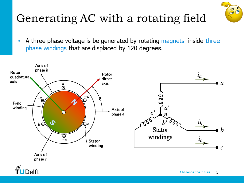
If there are magnets installed on the rotor, by rotating the rotor, there will be a rotating magnetic field generated in the air gap of the synchronous machine. As we have studied in the last lecture, there will be symmetric three phase voltages induced in the three phase winding if the three phases are displaced by 120 degree with each other.
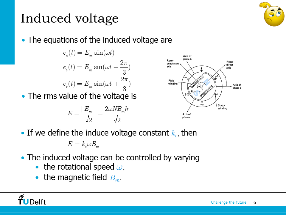
Assuming the rotor is rotating counter-clockwisely and the phase in phase is placed in the sequence of a-b-c as well, the three phase induced voltage can be described as
From the last lecture, if the number of turns of each phase is \(N\), the rotating angular speed is \(\omega\), the flux density amplitude is \(E_m\), the radius of the stator inner surface is \(r\), then the rms value of the induced voltage is
Apparently, the induced voltage is proportional to both the flux density and the rotating angular speed. The induced voltage constant is defined as \(k_e\), so
Therefore, the induced voltage can be controlled by varying either the rotational speed \(\omega\) and the magnetic field \(B_m\).
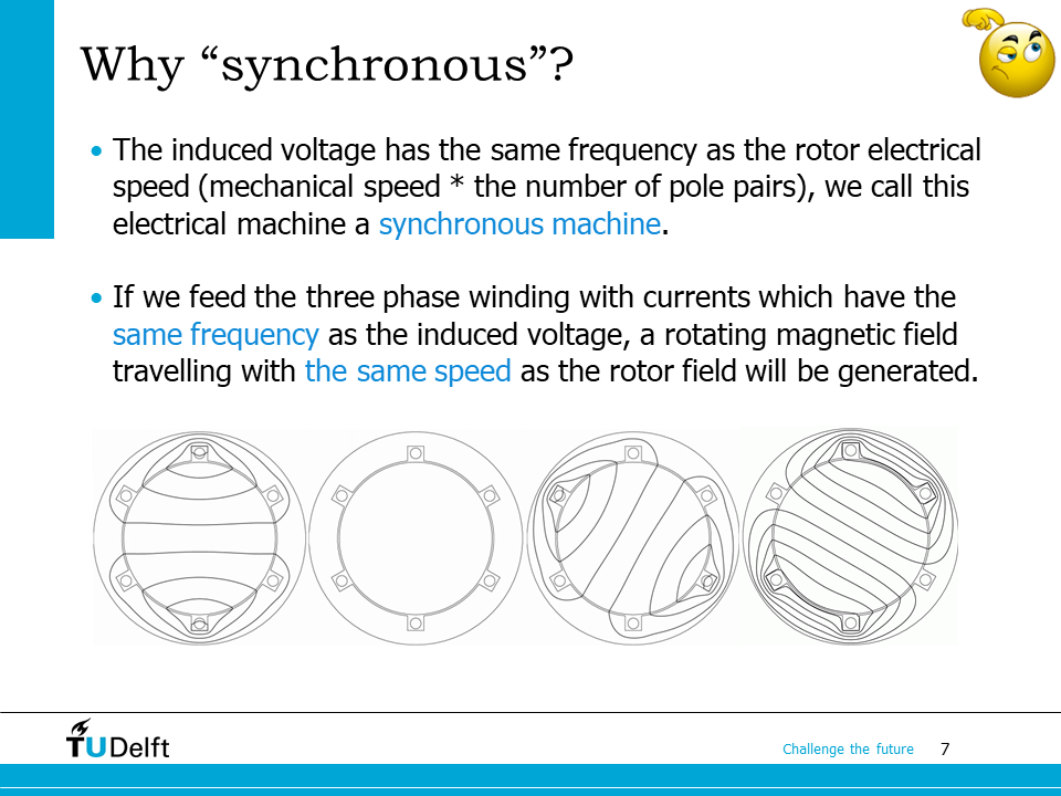
The induced voltage has the same frequency as the the rotor electrical speed \(\omega_e = p\omega_m\), where \(p\) is the number of pole pairs, \(\omega_m\) is the rotor mechanical angular speed. The rotor rotates at the synchronous speed, therefore, we call this type of electrical machine as synchronous machine.
If we feed the three phase winding with the three phase currents of the same phase sequence and the the same frequency as the induced voltage, from the three phase part of this course, we know a constant power transfer will be obtained.
If we study the magnetic field inside the air gap, we can see that a rotating magnetic field will also be generated by the three phase stator currents, which is travelling at the same speed as the magnetic field generated by the rotor winding.
23.2. Synchronous machine construction#
Then we study the structure of the synchronous machine.
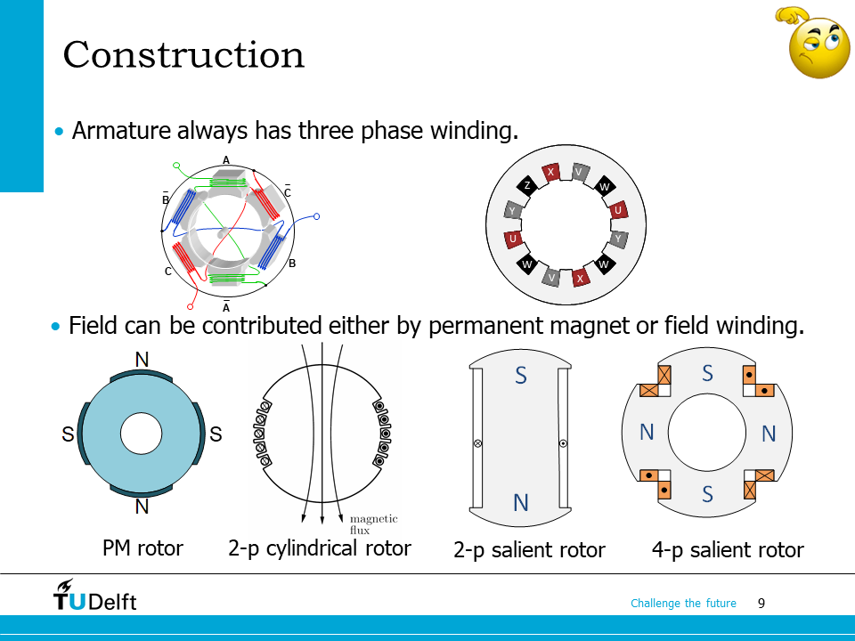
For the three phase synchronous machine, the stator armature always has a three phase symmetric winding.
On the rotor side, there can be several different structures. Depending on how the rotor magnetic field is generated, we have
- Permanent magnet rotor#
The rotor magnetic field is generated from the permanent magnets installed on the rotor.
- Wound field rotor#
The rotor magnetic field is generated from the field winding installed on the rotor.
Depending on whether the rotor has a smooth surface, we have
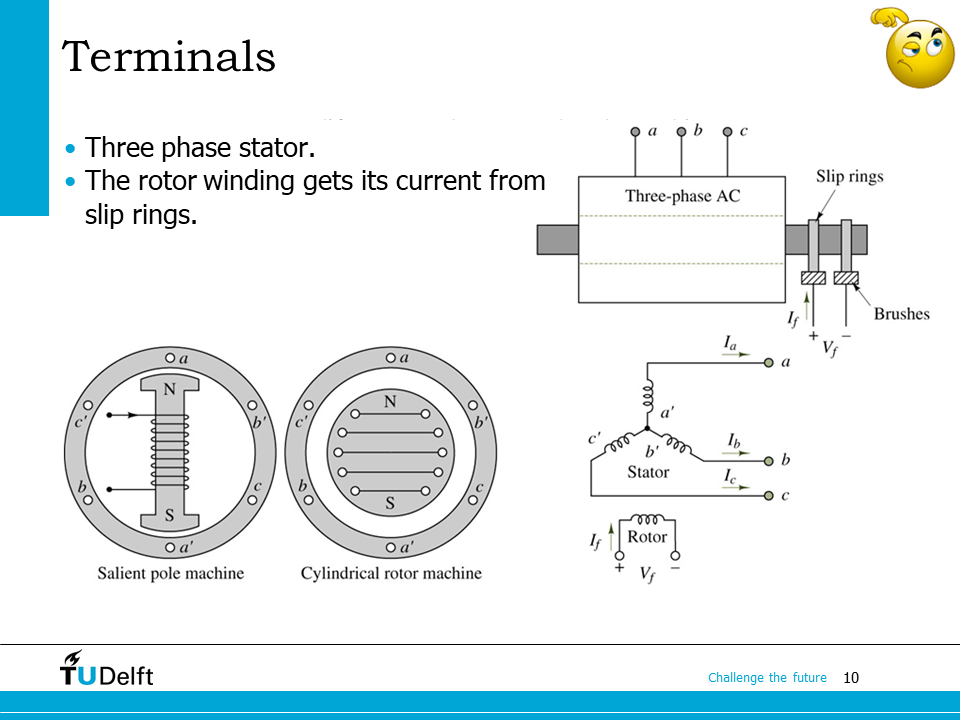
The stator has the three phase terminal to take or send three phase currents. The excitation current in the field winding has to be DC. In order to feed DC excitation current to the rotating rotor winding, a brush-slip ring mechanism is used. On the bottom right of the slide, you can find a simplified schematic of the synchronous machine.
23.3. Example#

Hereby we show some examples in practical applications of synchronous machines.
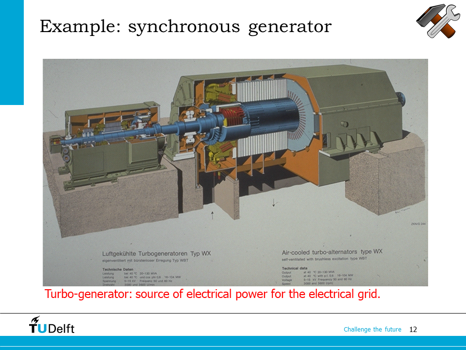
Synchronous machines are extensively used in electric power grid. What you see here is a synchronous machine used in a power plant, the left part of the setup is a excitation machine, which is used to generate the DC excitation current to feed the field winding. From the cross sectional view, we can see the synchronous machine is a non-salient synchronous machine. Usually non-salient synchronous generators used for power plants have 2 poles, and are used in high speed applications where the speed is high (3000 rpm for 50 Hz), e.g., thermal power plants and nuclear power plants. The prime movers in these applications are usually steam turbines or gas turbines.
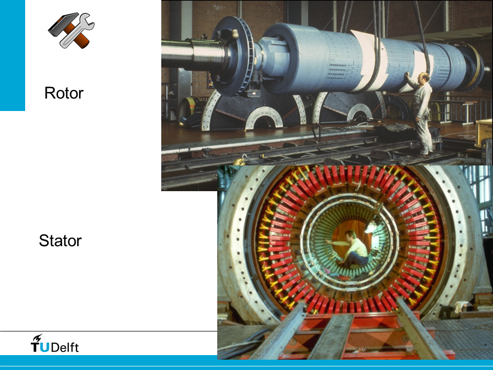
Here it shows the rotor and structure construction of a synchronous generator used for thermal power plant.
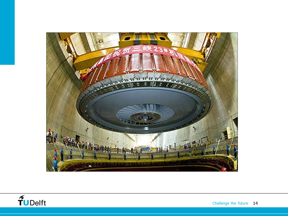
The photo here shows the installation moment of a synchronous generator in a water power plant. Usually salient pole synchronous generators are used in water power plants. The rotating speed is usually low, and the number of poles is high, so that 50 Hz or 60 Hz can be achieved at low speed.
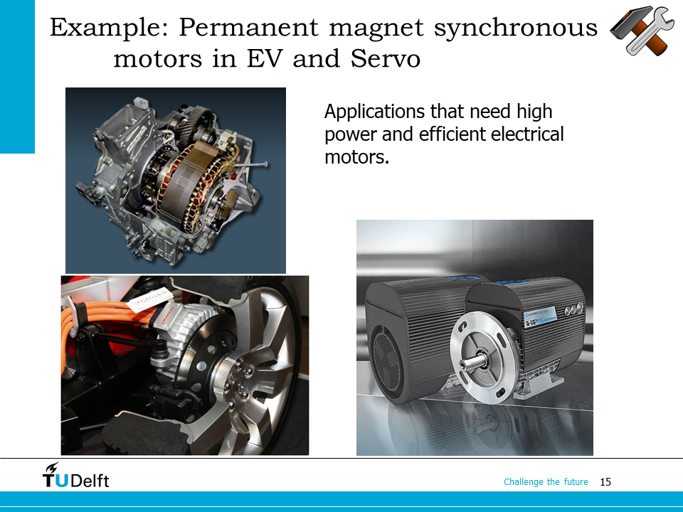
Apart from power generation, synchronous machines are also used in applications which require high power or high efficiency. For example, in modern servo applications and electric vehicles, permanent magnet synchronous machines are extensively used. Since the permanent magnetic synchronous generator do not need field current to generate the rotor magnetic field, they can result in high efficiency, compact size and improved dynamics.
23.4. Equivalent circuit#
Similar to the DC machine, the equivalent circuit can be used to calculate the performance of the synchronous machine.
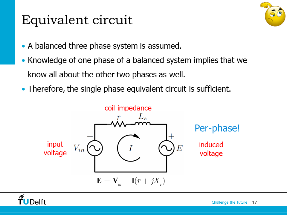
If we assume the three phase induced voltages and currents are balanced and symmetric, then we could just calculate the electrical performance from one phase. The three phase power can then be calculated by multiplying the single phase one by three. Therefore, it is sufficient to use the single phase equivalent circuit to calculate the performance.
The single phase equivalent circuit is shown on the bottom. The equivalent circuit here follows the motor notation. Furthermore, we assume the rotor is non-salient, so the phase inductance does not change as rotor rotates. The single phase input voltage \(\mathbf{V}_{in}\) and the phase induced voltage \(\mathbf{E}\) are both phasors. The phase impedance is placed in between, which should be a complex impedance since we are now dealing with an AC electrical circuit. Here \(X_s\) is also called the synchronous reactance.
23.5. Problem solving#
Now let us use the equivalent circuit to solve several problems.
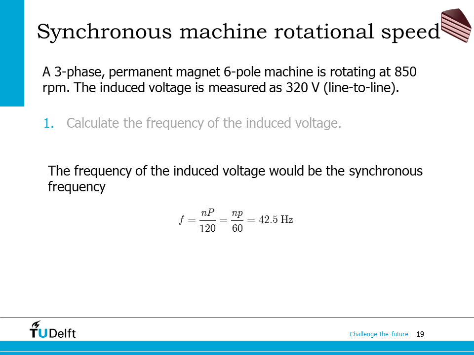
The first example is to calculate the frequency from number of poles, and the rotor rotating speed. If the number of poles is \(P\), the number of pole pairs would be
According to the relation between the electrical angle \(\theta_e\) and the mechanical angle \(\theta\): \(\theta_e = p\theta\), we have
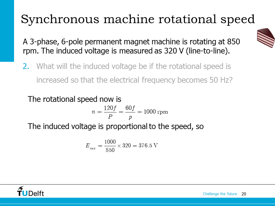
The induced voltage is proportional to the speed or the frequency, so we have
if we keep the excitation current unchanged.
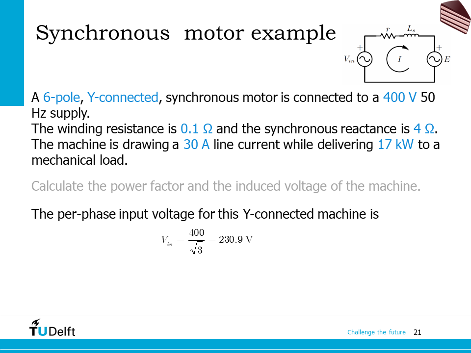
The second example is to calculate the power factor and induced voltage from the known power, the input voltage and the phase impedance.
First we have to convert the line to line voltage to the phase voltage.
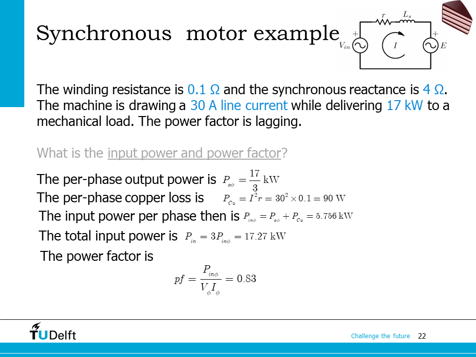
Since the machine is delivering power to a mechanical load, so the input power is
where \(P_{cu}\) is the stator copper loss, \(P_{out}\) is the output power.
Since the per-phase equivalent circuit i sued, here we convert the power to the per-phase power as well to calculate power factor.
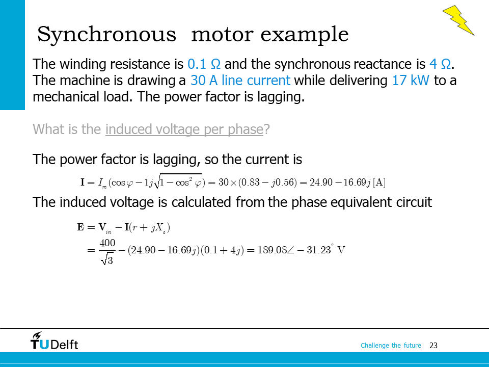
Once the power factor \(\mathrm{pf} = \cos \phi\) is known, we are able to obtain the complex current as
Here the sign of in front of the sine item is negative because the power factor is lagging.
Afterwards, the phase induced voltage is obtained from Kirchhoff’s voltage law,
Be aware that there the motor notation is used.
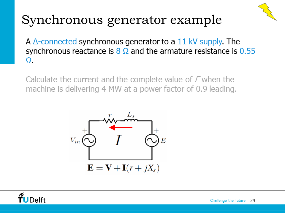
The example is is similar to the previous one. However, now we have to follow the generator notation.
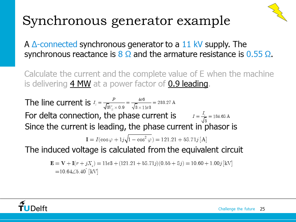
We first have to calculate the phase current from the power and the power factor. Pay attention that the synchronous machine is delta connected, so \(I_{line} = \sqrt{3} I_{\phi}\).
23.6. Homework#
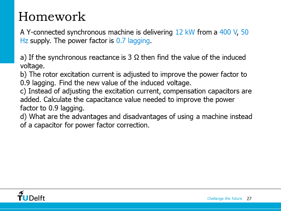
We may apply the equivalent circuit to solve the homework here. Please try to solve it yourself and check the script below for the right answer.
Show code cell source
import numpy as np
import cmath
from IPython.display import display, Markdown, Math, Latex
P   = 12.0e3
V_phi = 400.0/np.sqrt(3)
f   = 50.0
pf  = 0.7
lagging = -1

Xs = 3.0

# a). induced voltage
P_phi = P/3 # power per phase
I_phi = P_phi/V_phi/pf*(pf + 1j*lagging*np.sqrt(1-pf**2))

E_phi = V_phi - 1j*Xs*I_phi
print('a). The induced voltage is')
display(Math('$\mathbf{{E}}_\phi={:.2f}\\angle{:.2f}^\circ$'.format(abs(E_phi), cmath.phase(E_phi)/np.pi*180)))

# b). change of power factor
pf_new = 0.9
P_phi = P/3 # power per phase
I_phi = P_phi/V_phi/pf_new*(pf_new + 1j*lagging*np.sqrt(1-pf_new**2))

E_phi = V_phi - 1j*Xs*I_phi
print('b). New induced voltage is')
display(Math('$\mathbf{{E}}_\phi={:.2f}\\angle{:.2f}^\circ$'.format(abs(E_phi), cmath.phase(E_phi)/np.pi*180)))

# c). compensation with capacitor
# difference in reactive power
dQ = P_phi/pf*np.sqrt(1-pf**2) - P_phi/pf_new*np.sqrt(1-pf_new**2)
# added capacitance
C = dQ/(V_phi**2 * 2*np.pi*f)
print(f'c). Added capacitor is {C*1e6:.2f} uF.')

# d).

print('d). Compared to the capcitor based power factor compensation method: the synchronous machine has higher loss, higher cost and rotating part which is less reliable, but it can provide stepless compensation.')
a). The induced voltage is
b). New induced voltage is
c). Added capacitor is 127.93 uF.
d). Compared to the capcitor based power factor compensation method: the synchronous machine has higher loss, higher cost and rotating part which is less reliable, but it can provide stepless compensation.