25. Induction Machine#
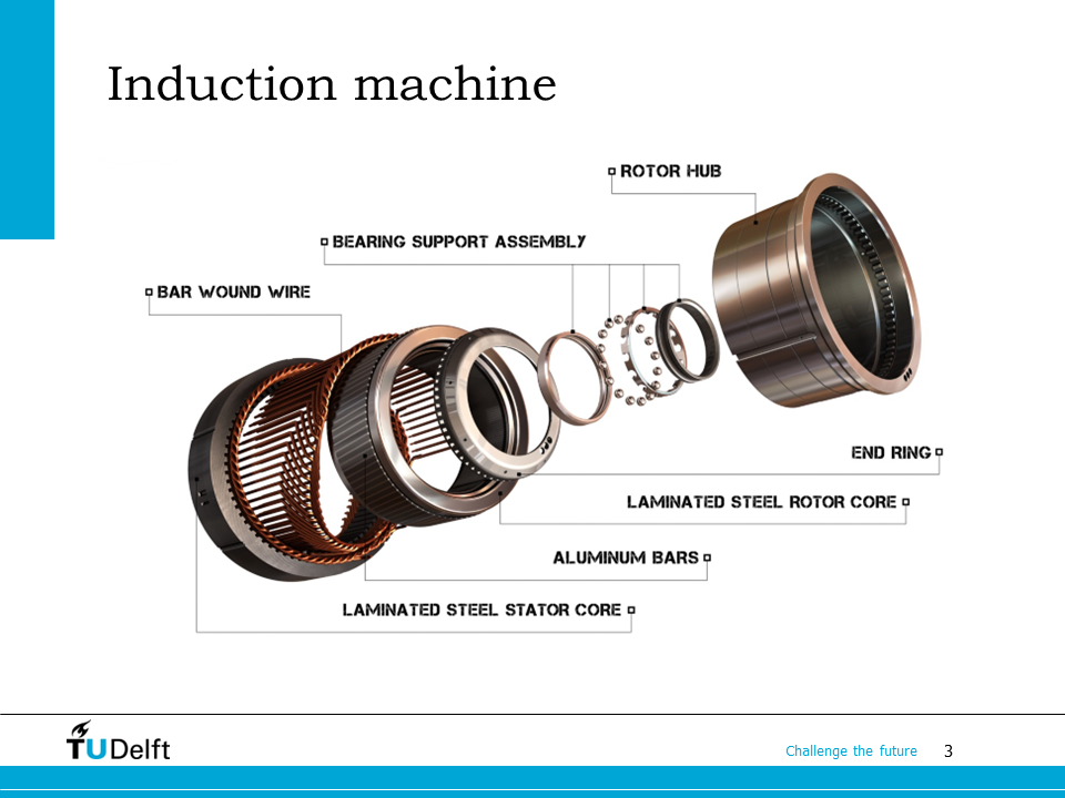
The exploded-view of the induction machine is shown here on the slide. The stator has the same structure as that of the synchronous machine. However, the rotor winding is composed of conducting bars, shorted by two end rings, which form a squirrel-cage like structure. Therefore, the induction machine shown here is also called squirrel cage induction machine. There is another type of induction machine, which has normal three phase winding on the rotor side as well, and is called doubly fed induction machine since both the stator and the rotor windings can be fed with three phase power. In this course, we will focus on the squirrel cage induction machine.
In the example shown on the side, aluminium bars are used to make the rotor squirrel cage. However, in high end applications, for example high speed induction machines used for compressors, or induction motors for electric cars, copper bars are also used. Since copper has higher conductivity, the copper bar induction machine can offer higher efficiency and higher power density.
After taking the lecture, we would be able to understand the construction and operation principles of the induction machine. The most important feature of the induction machine – slip – will be studied. The equivalent circuit model of the induction machine will be introduced and we should be able to apply it to solve problems.
25.1. Construction#

First let us study how the induction machine is constructed.
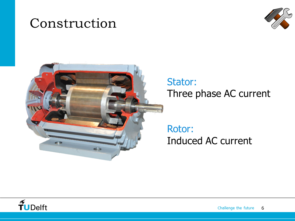
Unlike the induction machine, both the stator winding and the rotor winding (shorted bars or wounded coils) have AC current flowing inside them. The rotor current of the squirrel cage induction machine is caused by the induced voltage induced from the rotating magnetic field according to Faraday’s law.
A cut-view of an practical induction machine is shown on the slide. You can see the laminated stator and rotor cores, three phase stator windings, and two end rings of the rotor squirrel cage. There are fins attached to the two end rings, which can be used for the balancing of the rotor and cooling.
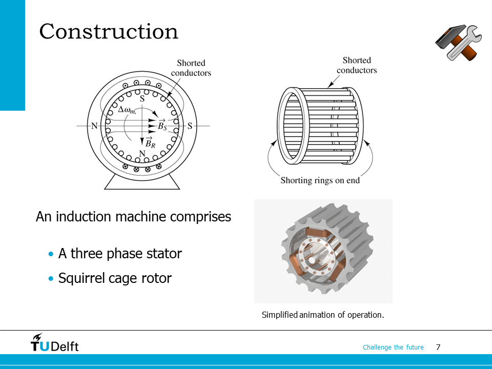
The structure of the squirrel cage induction machine is further explained here. You may notice in the animation below that the squirrel cage is skewed, i.e., the bars are not parallel to the shaft. The bars form an constant angle with respect to the shaft. The rotor skewing is used to reduce the torque ripples caused by the slotting effect.
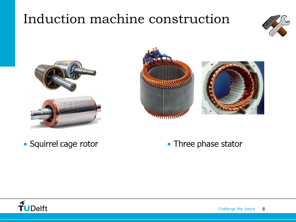
On this slide you can find more examples of the rotor and stator constructions for the induction machine.
25.2. Operation principle#

As the name indicates, the induction machine operates based on the Faraday’s law of induction. We will study its operation principle in detail using a simplified induction machine.
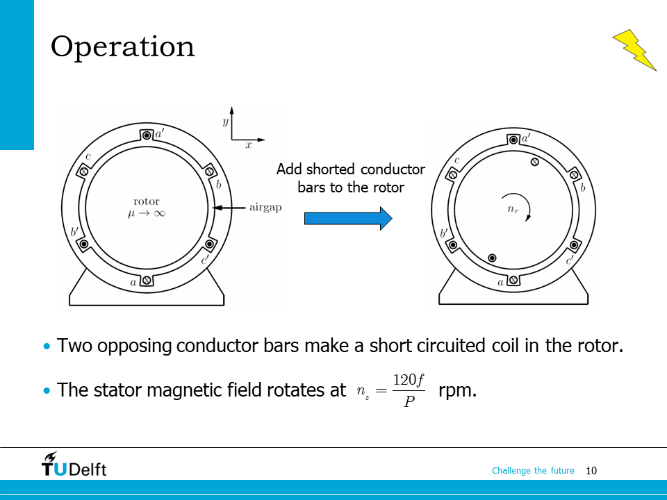
Similar to the synchronous machine analysis, we first assume the core has infinite permeability, and there are two magnetic poles. There three phase winding on the stator is assumed to be concentrated on the inner surface of the stator, so that the slots can be neglected. The rotor squirrel cage is approximated by a pair of opposing conductor bars, shorted by the end rings. The two conductor bars hence form a short-circuited coil.
If the frequency of the stator power supply is \(f\), the synchronous speed, i.e., the speed of the rotating magnetic field \(n_s\) in rpm is calculated as
where \(P\) is the number of poles.
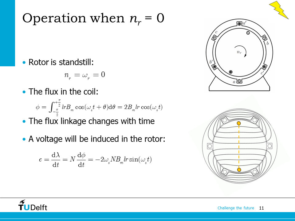
We first study the scenario when the rotor stays standstill, so the rotor speed \(n_r = 0\). The angular speed of the rotor \(\omega_r = 0\). From the AC Machine Stator part, we know the stator three phase current will generate a rotating magnetic field in the air gap:
where \(\omega_s\) is the synchronous angular speed, \(\omega_s = \frac{2\pi n_s}{60}\). Assuming the conductor pair are located at \(\theta = -\pi/2\) and \(\theta = \pi/2\) respectively, we can calculate the flux linked with the rotor shorted circuit,
where \(l\) is the axial length of the magnetic core, \(r\) is the radius of the air gap.
The induced voltage in the rotor conductor loop is then
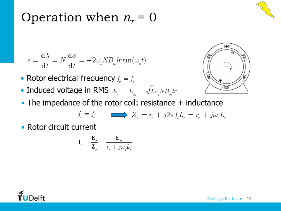
From the induced voltage equation, we can see that when the rotor is standstill, the frequency of the induced voltage in the rotor \(f_r\), is the same as the stator frequenc \(f_s\). The rms value of the rotor induced voltage would be
Here we define this voltage as \(E_m\).
The impedance of the rotor coil in this case will be
where \(r_r\) and \(L_r\) are the resistance and inductance of the rotor conductor loop.
The rotor circuit current phasor is then
Now we can see the induction machine operates as a transformer when the rotor is standstill.
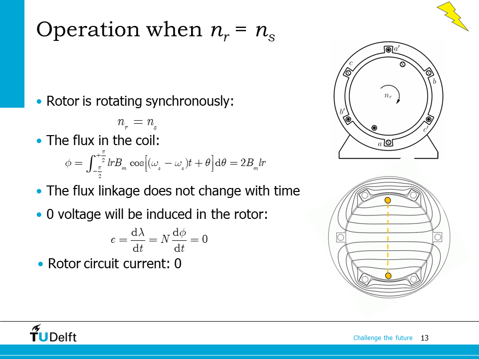
The second scenario is when the rotor rotates at the synchronous speed, so \(n_r = n_s\). In such as, the magnetic flux density distribution seen from the rotor coil be
The flux in the coil becomes
which is a constant, so the induced voltage in the rotor would be
The rotor circuit current would also be 0.
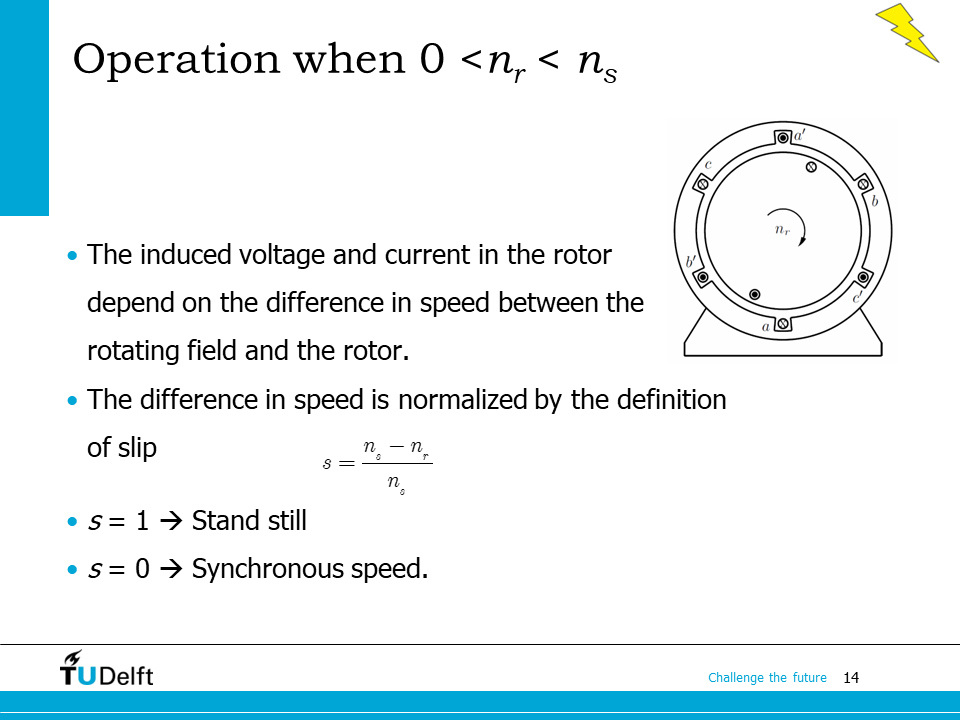
When the rotor rotates at a speed between 0 and the synchronous speed, there will certainly be voltage induced in the rotor circuit. However, the induced voltage and current in the rotor will be dependent on the difference in speed between the rotating magnetic field (synchronous speed \(n_s\)) and the rotor rotating speed \(n_r\).
To quantify the influence of the rotor speed on the induced voltage, we introduce the concept of slip, which is noted by the symbol \(s\), and is defined as
If \(s = 1\), then \(n_r = 0\), the rotor is standstill. If \(s = 0\), then \(n_r = n_s\), the rotor rotates at the synchronous speed.
25.3. Induction machine slip#

Now let us move on to the general case, when \(s\) is neither 0 nor 1.
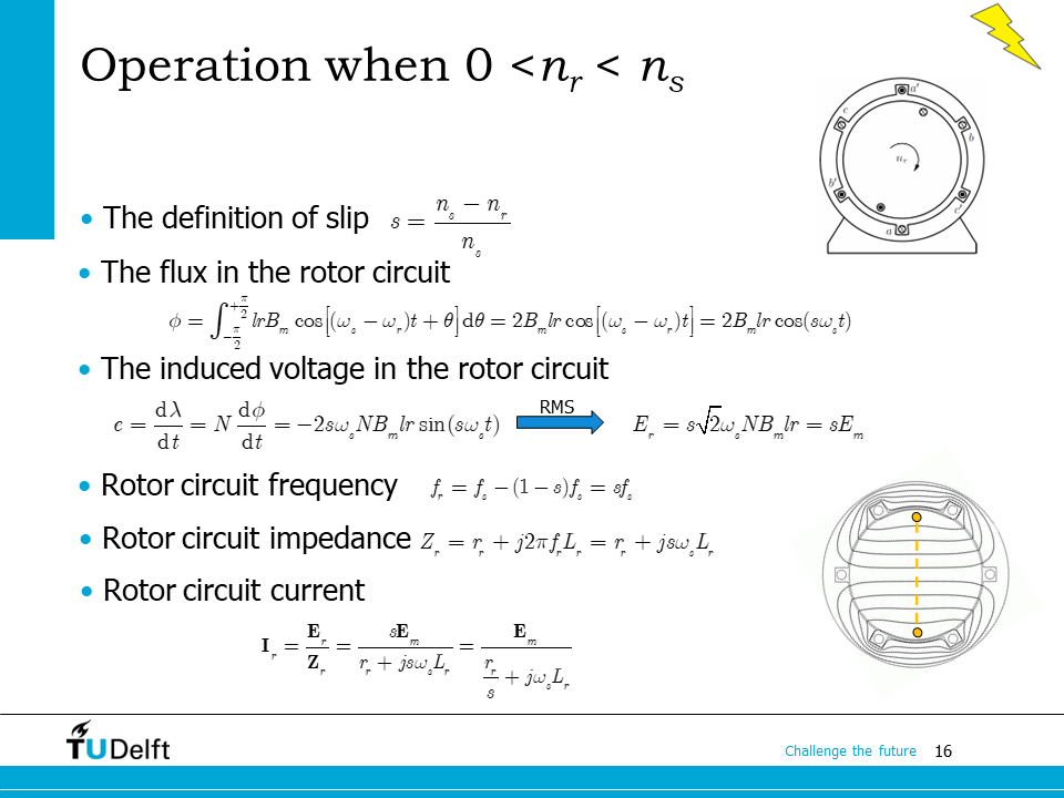
If the rotor travels at the angular speed \(\omega_r\), the flux density distribution seen by the rotor is
The flux linked with the rotor coil is then
The voltage induced becomes
The rms value of the induced voltage now becomes
Now the frequency of the rotor induced voltage becomes \(f_r = sf_s\).
The circuit impedance is
The rotor circuit current phasor is then
From the rotor current expression, we can see that, the current is equivalent to the standstill case, with the rotor circuit resistance divided by a factor of \(s\).
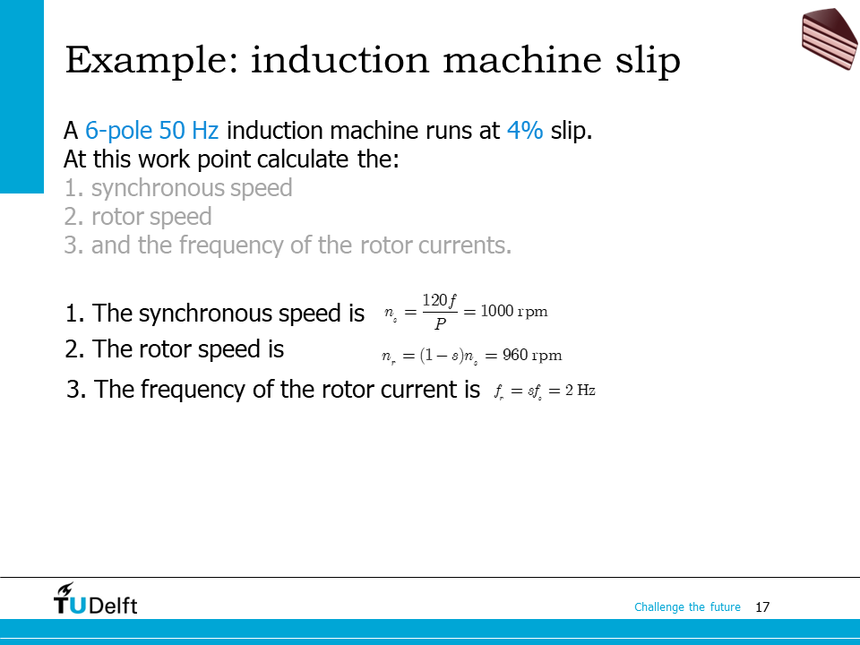
Let us use the example here to practice the slip related calculation. You have to know the three formulae below by heart, for the calculation of induction machine.
Synchronous speed:
where you have to pay attention to the difference between the number of poles \(P\) and the number of pole pairs \(p = P/2\).
The rotor rotating speed is \(n_r = (1-s)n_s\).
The electrical frequency of the rotor current is \(f_r = sf_s\), where \(f_s\) is the stator electrical frequency.
25.4. Equivalent circuit#

Like any other electrical machines, we may use the equivalent circuit based method to calculate the steady state performance of the induction machine.
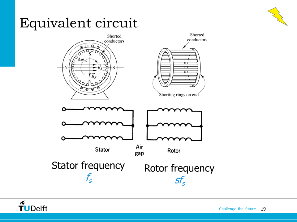
From the analysis in the last section, we know if the stator electrical frequency is \(f_s\), the rotor electrical frequency will be \(sf_s\). The stator circuit and the rotor circuit have different frequencies, so we are not able to connect them together to make a single equivalent circuit.
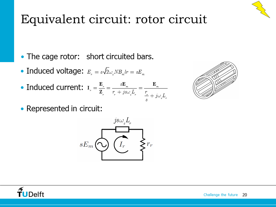
From the previous section, we know the induced voltage in the rotor circuit is \(E_r = s\sqrt{2}\omega_s N B_m lr = sE_m\), which is proportional to the slip \(s\). We are able to to represent the short-circuited rotor circuit as shown on the bottom of the slide. The electrical frequency of the rotor circuit is \(sf_s\).
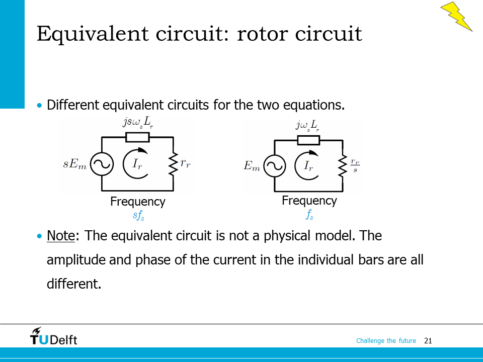
By dividing each item in the original equivalent circuit by the slip \(s\), we are able to derive its equivalence on the right hand side. As we can see, although the equivalent circuit on the right hand side has the frequency \(f_s\) instead of \(sf_s\), the current phasor in the rotor circuit stay the same, i.e.,
Attention
The equivalent circuit model we derive here is based on the simplified induction machine, and is not a physical model. The current phasors in individual bars are different from the calculated rotor current from the equation above.
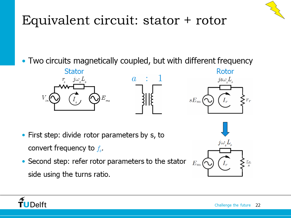
As we can see, by dividing the rotor circuit items by the slip \(s\), the rotor circuit can be converted to its equivalence operating at the stator frequency \(f_s\). Since the stator and the rotor circuits now operate at the same frequency, and both circuited are coupled via the same air gap magnetic field, it makes it possible to analyse them using the transformer principle.
If the turns ratio between the stator winding and the rotor winding is \(a\), then we can refer the rotor circuit parameters to the stator side and result in an equivalent circuit.
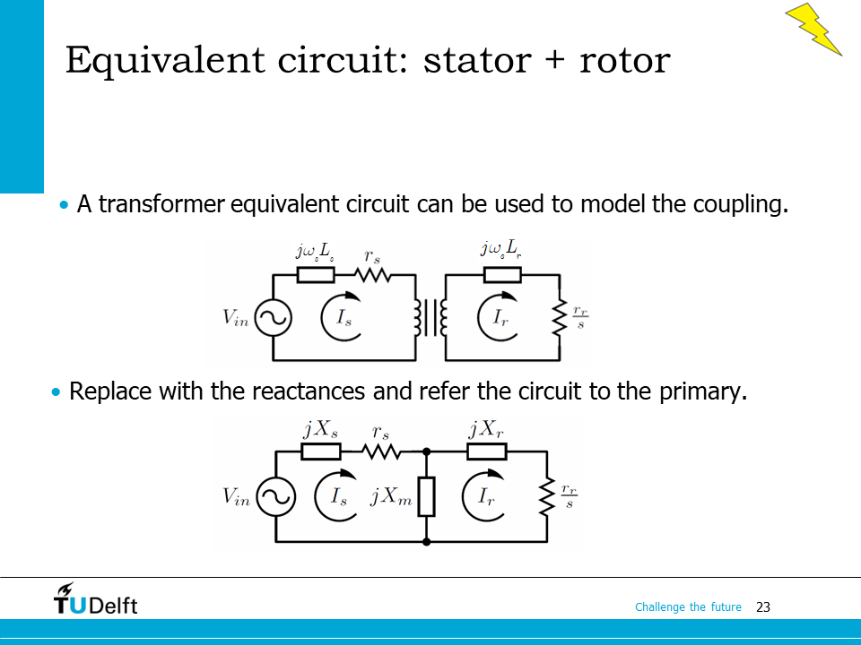
The figure on the top side of the slide shows the coupled circuit model of the induction machine. To simplify our analysis, we could follow what we do for the transformer: replace the coupled coil with the leakage inductances and magnetising inductance, then referring the rotor circuit parameters to the stator side.
An equivalent circuit as shown on the bottom is obtained after the transformations above. Here \(X_s = \omega_s L_s\) is the stator leakage reactance, \(L_s\) is the stator leakage inductance, \(X_r= \omega_s L_r\) is the rotor leakage reactance, \(L_r\) is the rotor leakage inductance, \(X_m = \omega_s L_m\) is the magnetising reactance, \(L_m\) is the magnetising inductance, and \(\omega_s\) is the stator electrical angular frequency.
25.5. Example#

An example is used here to show how to apply equivalent circuit to solve the induction machine related problem.
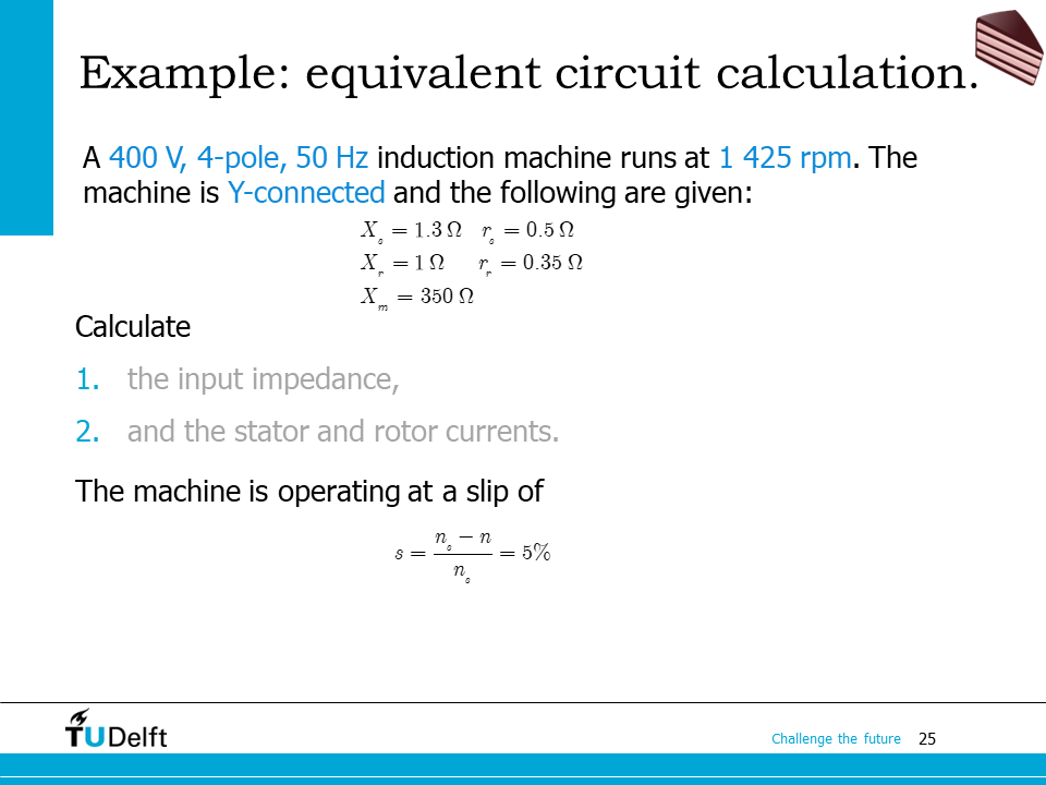
The questions here ask us for input impedance of the inductance machine with given circuit parameters, and the stator/rotor currents. To solve for them, we first have to calculate the slip \(s = \frac{n_s-n}{n_s}\), where the synchronous speed \(n_s\) is solved as
Actually the rated slip of normal induction machines is usually a small value(< 0.1), so from the rotating speed of the induction machine and the frequency, we are able to calculate the synchronous speed and the number of poles. For example, a 50 Hz induction machine with rated speed of 2980 rpm has 2 poles, and a 50 Hz induction machine withe rated speed of 1425 rpm should be a 4-pole machine.
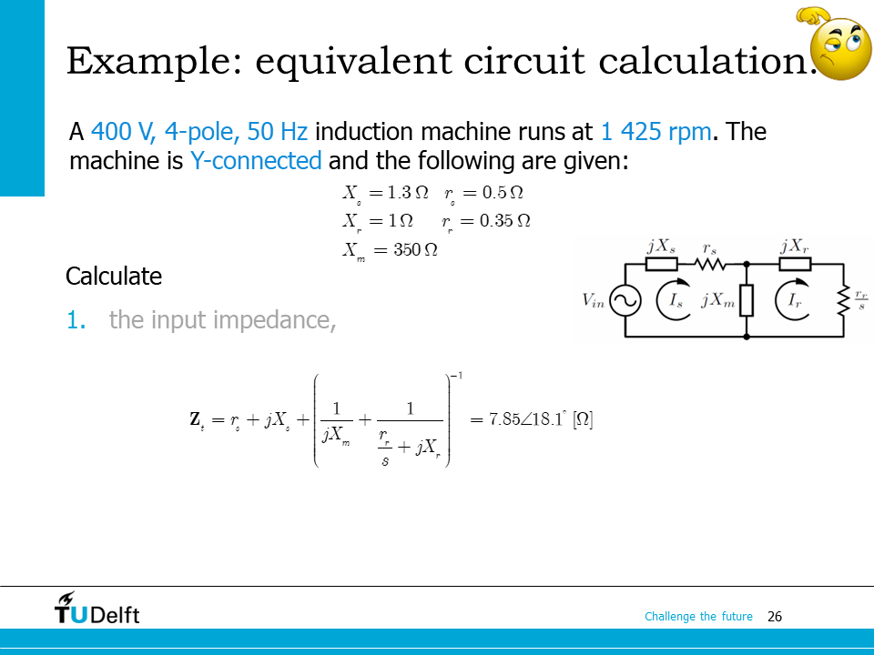
From the series and parallel connections in the equivalent circuit, we know the total input impedance would be
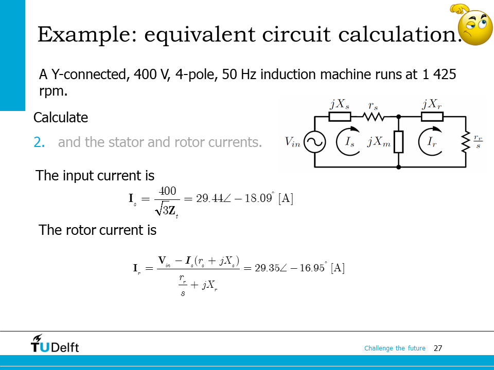
The rotor current is calculated from the rotor voltage and the rotor circuit impedance. The rotor voltage phasor would be:
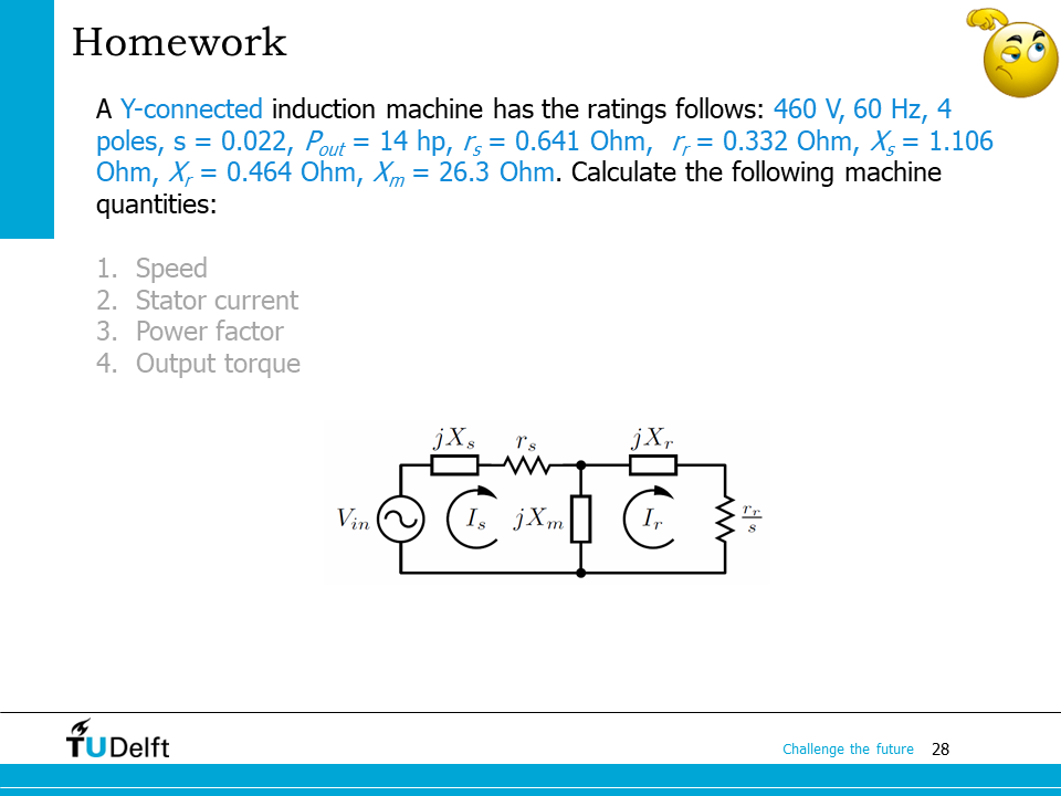
Please take this example as your homework. Please first try to solve it yourself before clicking the script below for the correct answer.
Show code cell source
import numpy as np
from IPython.display import display, Markdown, Math, Latex

V_ll = 460.0
f    = 60.0
P    = 4
s    = 0.022
P_out = 14.0*745.7 # convert to watts
r_s   = 0.641
r_r   = 0.332
X_s   = 1.106
X_r   = 0.464
X_m   = 26.3

# 1. speed
# synchronous speed
n_s = f*60/(P/2)
# rotor speed
n   = (1-s)*n_s
print(f'1. The rotor speed is {n:.2f} rpm.')

# 2. stator current
# input impedance
Z_in = r_s + 1j*X_s + (1/(1j*X_m)+1/(1j*X_r+r_r/s))**(-1)
V_ph = V_ll/np.sqrt(3)
I_s  = V_ph/Z_in
print(f'2. The input current phasor is {I_s:.2f} A, or')
display(Math('$\mathbf{{I}}_s={:.2f}\\angle{:.2f}^\circ \mathrm{{A}}$'.format(abs(I_s), np.angle(I_s)/np.pi*180)))

# 3. Power factor
print(f'3. The power factor is pf = {I_s.real/abs(I_s):.2f}.')

# 4. output torque
omega_m = n/60*2*np.pi # mechanical angular speed of the rotor
T = P_out/omega_m
print(f'4. The output torque is T = {T:.2f} Nm.')
1. The rotor speed is 1760.40 rpm.
2. The input current phasor is 15.72-10.48j A, or
3. The power factor is pf = 0.83.
4. The output torque is T = 56.63 Nm.