Module 2 Online Practical Manual: Electric Drives#
Introduction#
In this module we use a permanent magnet synchronous machine driven by an in-house developed motor drive and an induction machine connected to the grid to measure the torque speed characteristic of the induction machine.
The deliverable of this module will be a practical report as per requirements given in each assignment.
To help you with questions and technical difficulties, a help desk is available. Please contact Joris Koeners via email if you have any questions and if needed a skype session can be planned.
Assignment 1: Preparation#
Please read
AC Machines part of the EE2E11 reader;
and the theoretical background section of this manual.
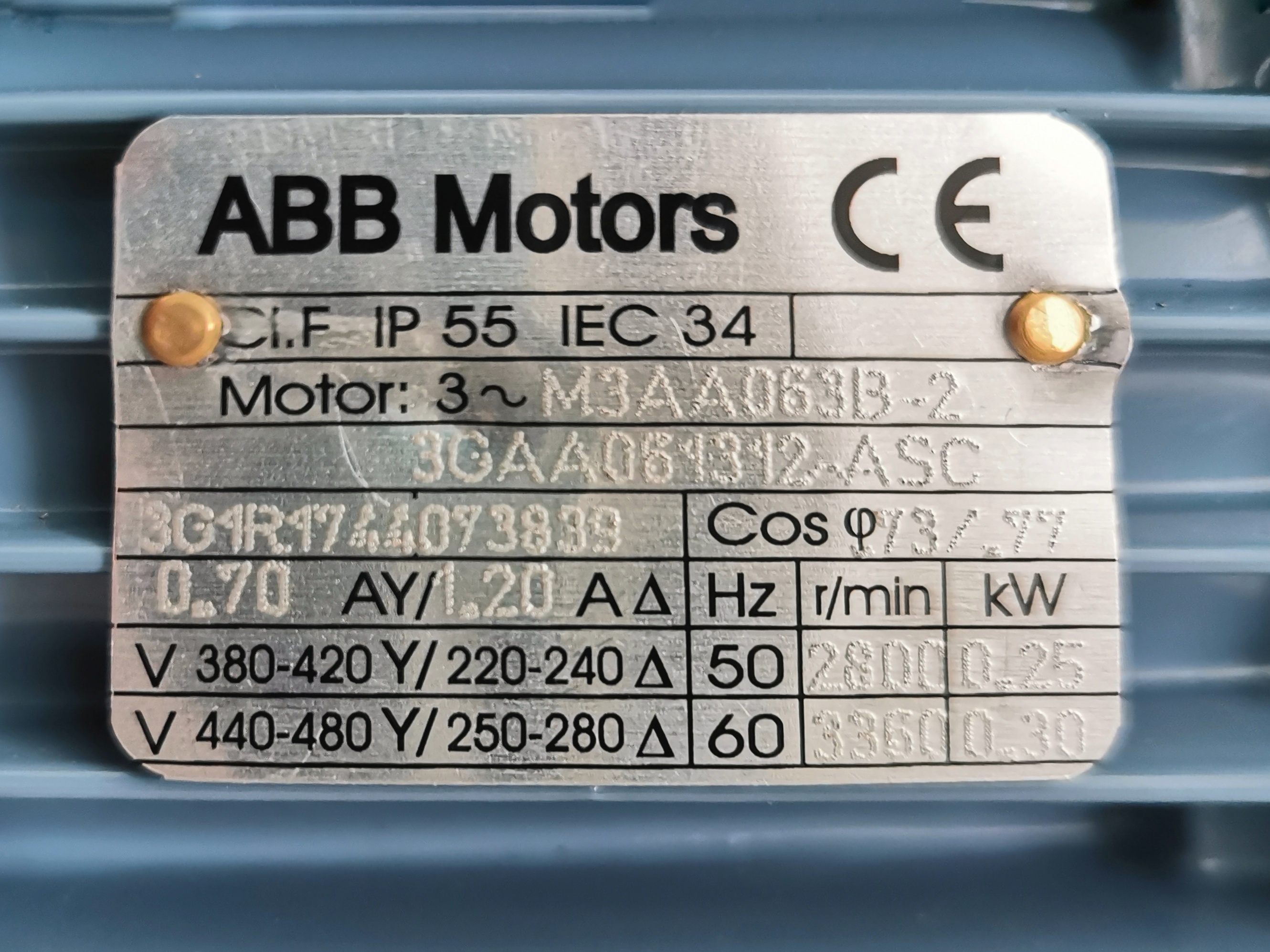
Fig. 14 The nameplate of the induction machine to be measured.#
Parameters |
Value |
Parameters |
Value |
|---|---|---|---|
\(r_s\) |
\(33~\Omega\) |
\(r_r\) |
\(29~\Omega\) |
\(L_s\) |
\(16.6~\mathrm{mH}\) |
\(L_r\) |
\(144.6~\mathrm{mH}\) |
\(L_m\) |
\(1.583~\mathrm{H}\) |
Assignment 1 of module 2 can be done at home without using the online practical platform.
The nameplate of the induction machine to be measured is shown in Figure 14. Equivalent circuit parameters of the induction machine are listed in Table 2.
Please include the following content in section 1 of the practical report of module 2:
Derive the number of pole pairs of the induction machine from the nameplate as shown in Figure 14;
Tell whether the machine should be configured in \(\Delta\) or Y connection when it is connected to the power grid in the Netherlands and give your justification;
Calculate and plot the torque-speed characteristic of the induction machine when the speed changes from 0 to 6000 rpm.
Tip
You may use MATLAB or Python/Matplotlib to do the calculation and plotting.
Assignment 2: Measurements of a grid connected induction machine#
You can do assignment 2 once you finish assignment 1. You will be able to login to the remote lab reservation system using your netid at http://remotelab.rs.tudelft.nl. You may reserve one time slot from available ones. When reserving the slot, please choose EE2E11_Module2_Machine from Select a resource dropdown menu on the reservation website to make the reservation. Once you have done that, you will receive an email with a link. The same link is also listed on the reservation website http://remotelab.rs.tudelft.nl. Please use the link to access the remote practical panel to do the practical. You will see a back-to-back electrical machines setup in the TU Delft lab and an operation panel on your web browser at the reserved time slot. There is another watching link sent to you which can be used to watch how you do the practical. You may share the link with your peers or the instructors if you want them to help you. You are allowed to reserve another time slot if you finish the last one.
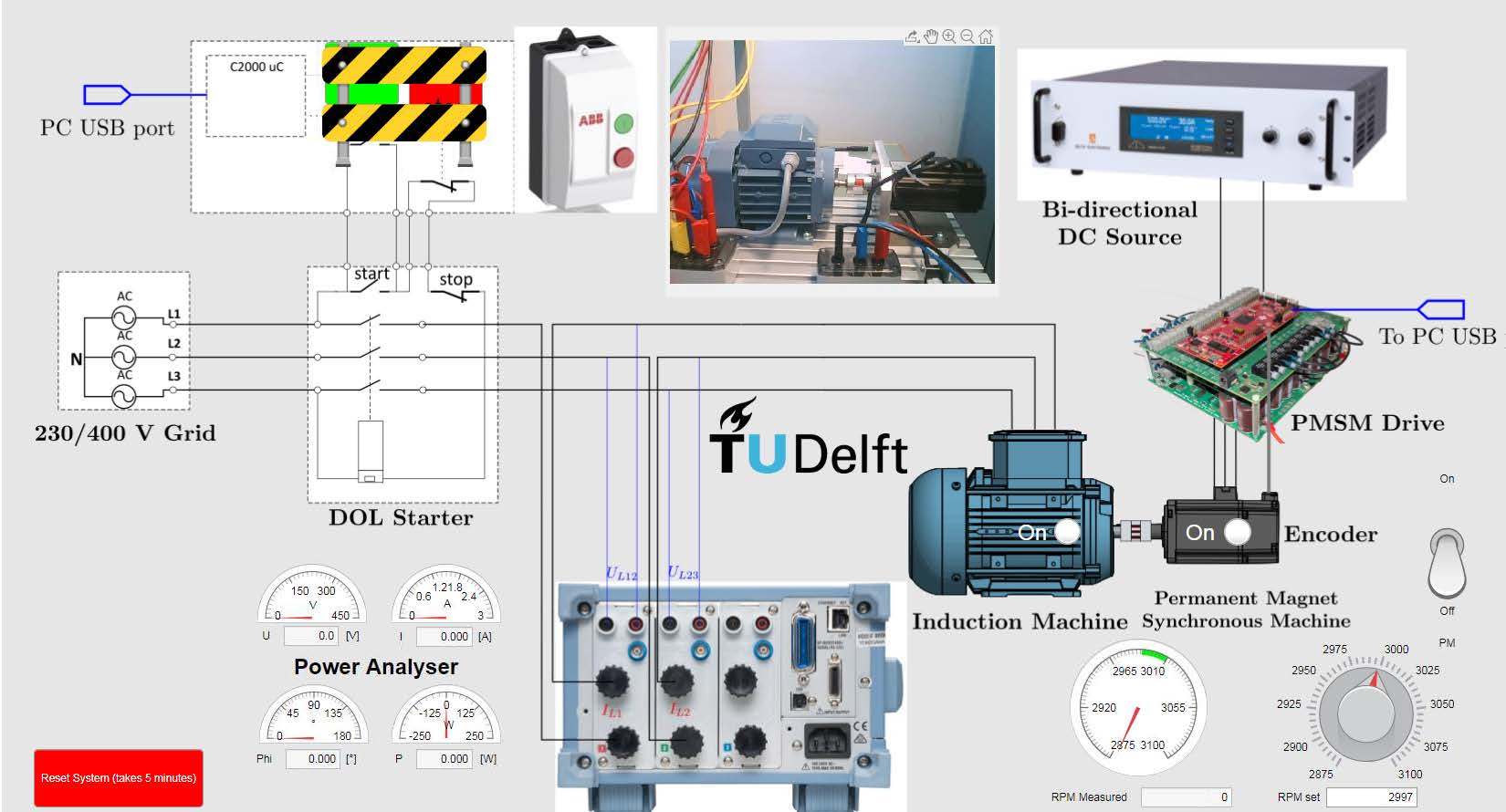
Fig. 15 Remote practical operation panel of assignment 2.#
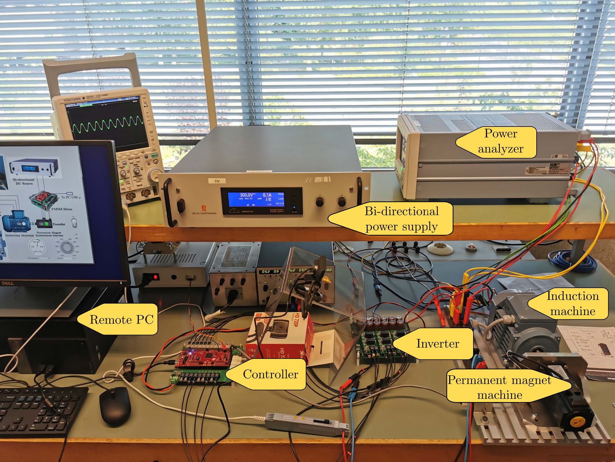
Fig. 16 Remote practical setup of assignment 2.#
Warning
Please refresh the online practical web page if the setup becomes unreponsive during the online practical.
The operation panel and the lab setup of module 2 are shown in Figure 15 and Figure 16 respectively. The schematic on the operation panel shows the structure of the lab setup: the induction machine is coupled to a permanent magnet synchronous machine (PMSM). The winding of the induction machine is connected to the 230/400 V grid through a DOL starter, which can be controlled remotely by clicking the green button to start or the red button to stop. A power analyser is connected between the DOL and the induction machine to measure the electrical power of the induction machine. The measured line voltage, line current, power factor angle and the total power can be read from the four meters on the left hand side of the power analyser on the panel. The rotational speed of the backto- back machine setup is controlled by the PMSMdrive. The reference speed can be set via the knob on the bottom right of the panel. The measured speed is shown on the meter next to it. The PMSM drive can be turned on/off by the switch above the speed knob. The two lights on the two machines indicate whether the twomachines are turned on or not.
Please follow the procedure below to do the measurements:
Set the reference speed to be around 3000 rpm;
Turn on the PMSM drive and wait for the machines to reach the reference speed around 3000 rpm;
Start the induction machine by clicking the start button of the DOL;
Measure the power and current of the induction machine via the power analyser, and note down themeasurements;
Change the speed of the machines, andmeasure the power and currentwhen the measurement stabilises, and take a note of themeasurements;
Repeat step 4 at eight or more speed points between 2875 rpm and 3100 rpm.
Set the reference speed back to 3000 rpm;
Disconnect theDOL by clicking the stop button of the DOL when the machines are around 3000 rpm.
Turn off the PMSM drive.
Please be aware that the DOL can only be started/stopped when the speed is around 3000 rpm (the green region in the speed meter) to avoid impulse to the grid, and the PMSM drive is only allowed to turn off when the DOL is disconnected.
After the practical, please work on the measured results, and include the following content in section 2 of the incremental report of module 2:
Draw a schematic of the setup including the inverter for the PMSM, the two machines and the DOL;
The PMSM machine is only half the size of the induction machine. However, the rated torque of the PMSM is 60% larger than that of the induction machine. Please give an explanation to that using the knowledge you learnt in the course;
A table summarizes the measurement results;
Calculate the electromagnetic torque of the induction machine at the measured points, using the phase resistance, measured speeds, currents and power;
Compare your torque-speed points obtained from measurements with the calculated torque-speed characteristic plotted in assignment 1. Reflect on differences if there are any.
Explain why the rotational speed range in the practical is limited between 2875 rpm and 3100 rpm, i.e., why should not we vary the speed between 0 and 6000 rpmto obtain a more complete torque-speed characteristic curve.
Tip
Please be aware that the power flow may change its direction, which has a consequence on the calculation of electromagnetic torque.
Please submit the report for module 2 to Brightspace course page under Assignments -> Practical module 2, final report. The deadline is 1st November, 2023.
Theoretical background: induction machine#
Winding connection induction machine#
The winding of the three-phase induction machine can be wired in different ways, as shown in Figure 17 Depending on whether the winding is connected in \(\Delta\) or Y, the induction machine will have different rated voltage and current when connected to the three-phase power grid. However, the rated power remains the same.
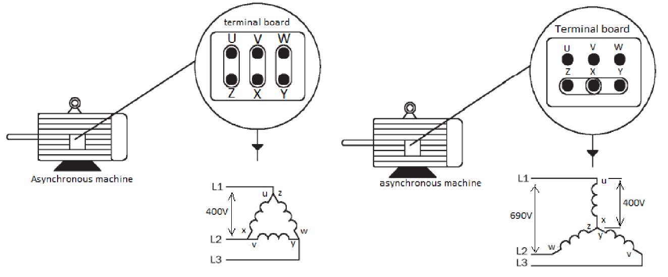
Fig. 17 Different methods to connect the induction machine using the terminal board.#
Grid connection#
The equivalent circuit of the induction machine is shown in Figure 18. There are 5 elements in the circuit: the stator resistance \(r_s\) , the stator leakage reactance \(X_s\) , the magnetizing reactance \(X_m\), the rotor leakage reactance \(X_r\) , and the rotor resistance \(r_r\) . The slip \(s\) is calculated from the synchronous speed \(n_s\) and the mechanical speed \(n\):
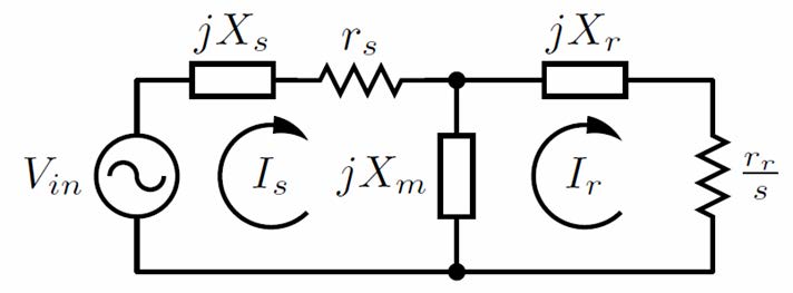
Fig. 18 Equivalent circuit of the induction machine.#
Connecting an inductionmachine ismore complicated than plugging the electrical cord. As can be seen from Figure 18, when the induction machine starts, the slip \(s=1\). Therefore, the rotor impedance is very low, which results in a high starting current even if there is no load. To protect the machine and the grid from overload or overcurrent, a direct-on-line (DOL) starter is often used. It connects the inductionmachine directly to the power grid via a three-phase contactor. Inside the starter, there are also overcurrent and overload protections connected in series with the contactor, as shown in Figure 19.
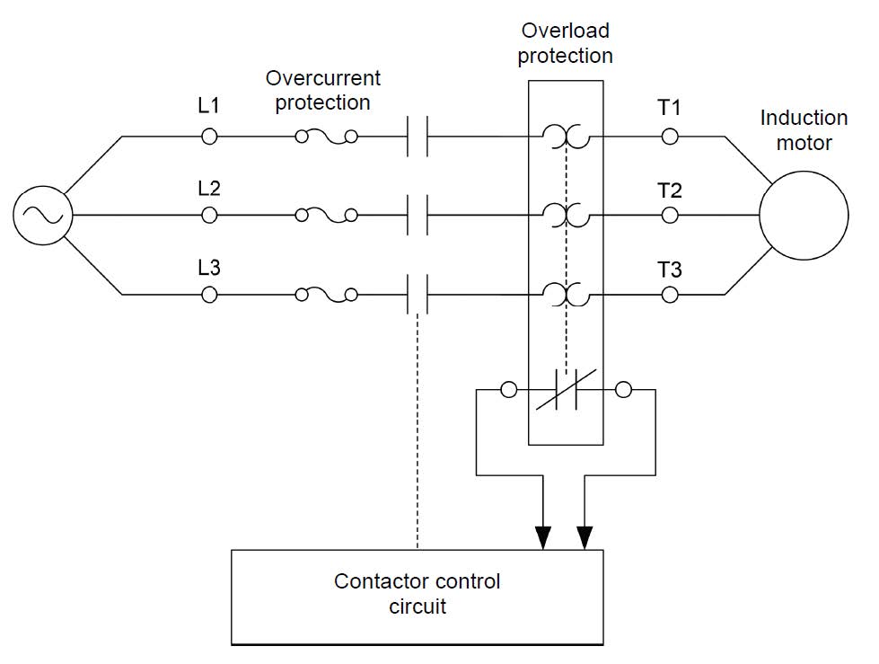
Fig. 19 Schematic of a DOL starter.#
Torque-speed characteristic#
The performance of the induction machine can be calculated from its eqivalent circuit in Figure 18. Once the frequency, phase voltage, and the resistances/inductances are know, the stator and rotor impedances and currents can be calculated at each slip. The air-gap power \(P_{ag}\) and the mechncial power \(P_{mec}\) are calculated is:
where \(P_{in} = 3\Re(\mathbf{V_s} \mathbf{I_s}^*)\) is the input power, \(\mathbf{V_s}\) is the stator phase voltage phasor, \(\mathbf{I_s}\) and \(\mathbf{I_r}\) are the phase stator current and rotor current phasors respectively.
When \(s=0\), the electromagnetic torque becomes 0 since it is corresponding to the no-load condition.
The electromagnetic torque \(T\) can be calculated from either the air-gap power or the mechanical power by
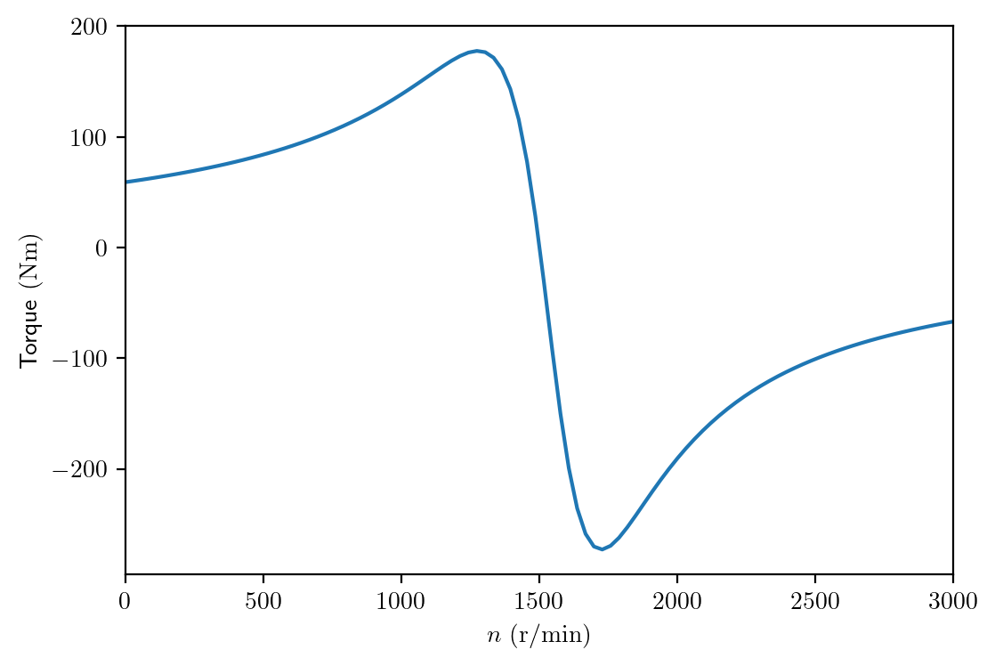
By substituting \(s\) and \(n\) into the equations above, the torque at different mechanical speed can be calculated. Therefore, a torque-speed characteristics curve can be plotted. The code below shows the torque-speed curve of a typical 4-pole induction machine. As we can see, the torque changes from positive to negative at the synchronous speed 1500 r/min.
import numpy as np
import matplotlib
matplotlib.rcParams['text.usetex'] = True
import matplotlib.pyplot as plt
plt.rcParams['figure.figsize'] = [6 , 4]
plt.rcParams['figure.dpi'] = 200 # 200 e.g. is really fine, but slower

# IM: 400 V, 4-pole, 50 Hz, Y connected
Ls = 4.138e-3
rs = 0.5
rr = 0.35
Lr = 3.183e-3
Lm = 1.114
f  = 50
Vll= 400.0
p  = 2  # 4-pole

Xs = 2*np.pi*f*Ls
Xr = 2*np.pi*f*Lr
Xm = 2*np.pi*f*Lm

Vph = Vll/np.sqrt(3) # Y connected
f   = 50.0
ns  = 60*f/p  # 4-pole
omegas = 2*np.pi*f # electrical angular speed


# calculate in array
n = np.linspace(0, 3000, 100)
s = (ns-n)/ns

Zr = np.divide(rr,s) + 1j*Xr
Zm = 1/(1/(1j*Xm)+1/Zr)
Ztot = Zm + rs + 1j*Xs

Is   = Vph/Ztot
Pin  = 3*np.real(Vph*np.conj(Is))
Pag  = Pin - 3*np.absolute(Is)**2*rs
T    = Pag/(ns/60*2*np.pi)

plt.plot(n, T)
plt.xlabel('$n~(\mathrm{r/min})$')
plt.ylabel('Torque$~(\mathrm{Nm})$')
plt.xlim([0, 3000])
plt.show()
Warning
Please be informed that the induction machine we use in the practical is not the same as the machine shown in the example above.